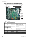
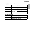
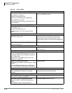
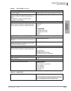
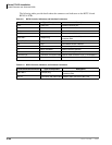
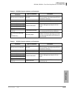
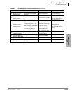
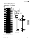
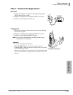
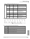
Station Apparatus
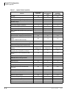
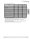
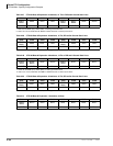
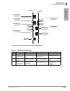
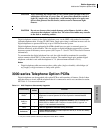
3000-series Telephone Option PCBs
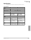
Strata CTX I&M 06/04 11-11
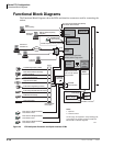
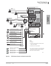
Station Apparatus
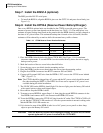
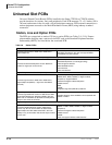
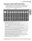
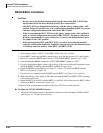
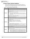
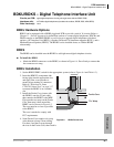
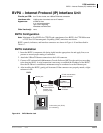
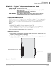
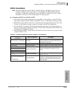
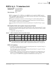
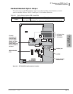
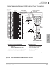
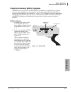
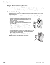
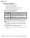
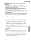
TAPI and Simultaneous Voice and Data Upgrades for 3000-
series Telephones (BPCI)
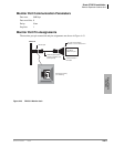
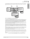
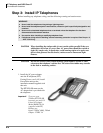
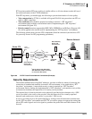
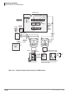
Digital telephones can be upgraded with a Personal Computer Interface (PCI) to provide desktop
interface with the telephone and PC USB port. The PC connected to the BPCI can place telephone
calls, receive Caller ID, ANI, and DNIS information. The BPCI is compatible with Microsoft
TAPI application programs.
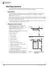
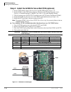
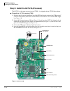
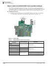
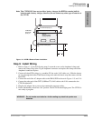
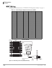
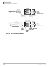
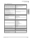
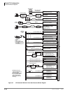
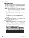
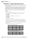
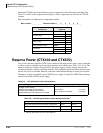
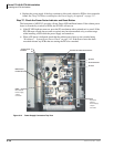
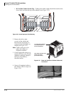
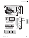
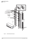
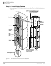
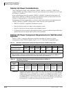
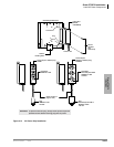
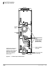
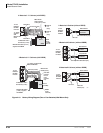
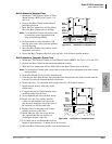
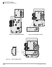
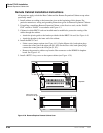
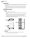
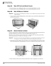
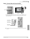
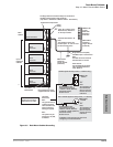
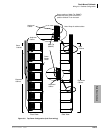
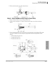
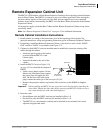
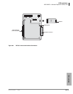
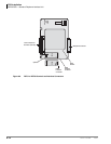
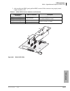
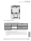
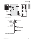
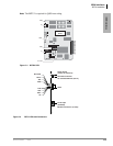
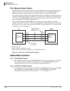
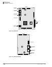
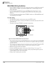
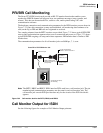
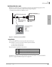
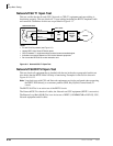
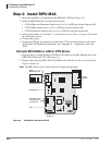
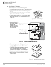
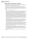
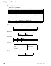
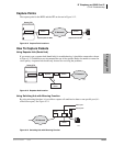
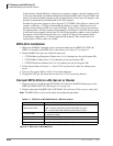
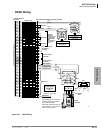
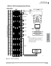
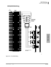
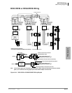
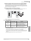
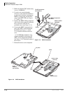
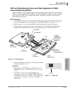
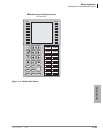
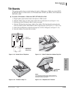
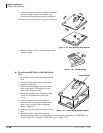
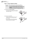
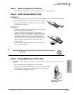
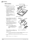
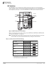
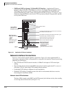
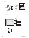
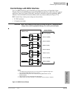
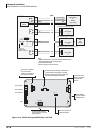
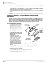
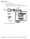
BPCI Installation
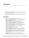
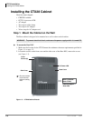
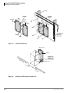
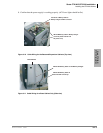
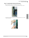
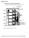
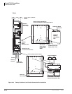
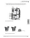
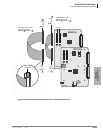
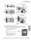
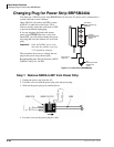
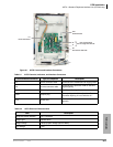
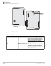
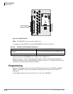
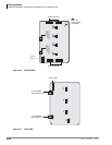
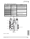
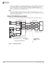
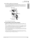
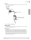
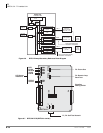
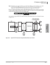
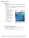
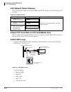
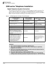
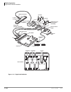
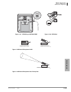
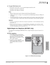
1. Loosen the four captive screws on the digital telephone base to remove it. Knock out the plastic
cover on the telephone base to provide access to the BPCI USB port. See Figure 11-10.
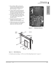
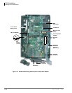
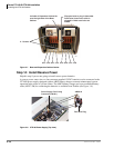
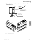
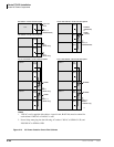
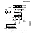
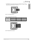
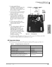
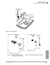
2. Refer to Figure 11-10 and install the BPCI inside the phone base. Secure with screws.
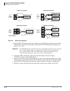
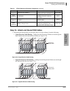
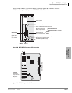
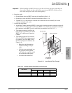
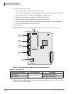
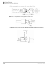
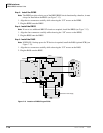
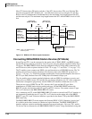
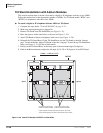
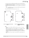
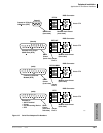
3. Insert the three integrated unit wire plugs into connectors P1, P2 and P6 on the PCB in the
telephone. Make sure that the red wire is positioned as shown. (P1-P1, P2-P2, P6-P4.)
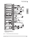
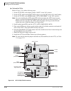
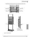
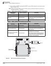
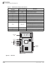
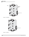
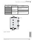
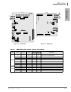
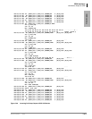
Figure 11-10 BPCI Installation
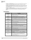
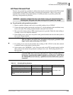
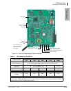
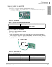
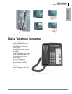
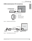
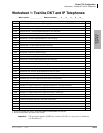
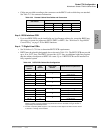
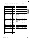
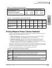
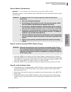
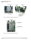
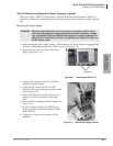
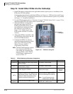
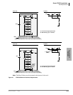
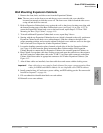
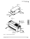
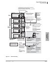
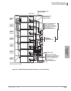
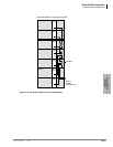
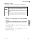
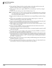
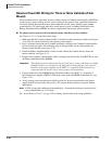
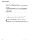
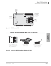
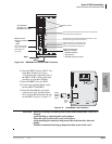
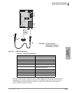
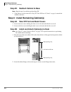
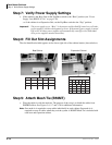
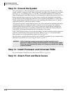
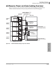
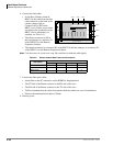
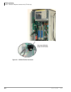
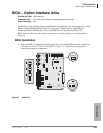
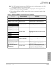
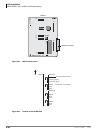
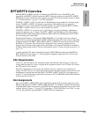
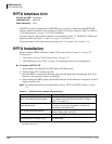
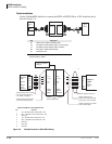
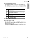
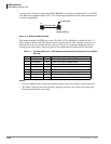
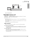
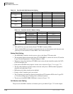
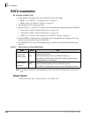
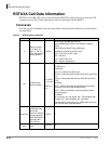
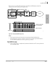
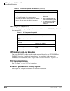
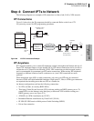
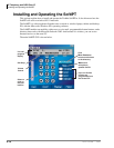
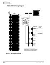
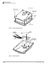
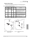
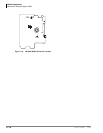
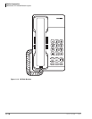
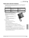
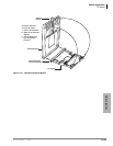
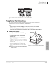
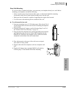
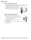
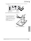
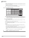
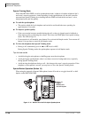
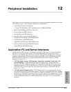
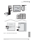
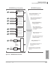
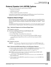
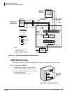
4. Stick the USB label onto the base, just below the modular
cord port (see Figure 11-11).
Important!
• BPCI requires a DKT3000-series telephone set in the
DKT3000 mode (see “DKT2000 Mode On/Off” on page
11-19).
• The BPCI also requires that the DKT3000-series
telephone be connected to a BDKU or BDKS PCB set to
the “BDKU” mode (not the “PDKU” mode). BPCI will
not function on a telephone connected to a PDKU or
RDSU PCB.
Digital
Telephone
Top Assembly
Digital
Telephone Base
PC USB
Connection
Port (knock out
plastic cover
on telephone
base)
(P1)
Install
Two Screws
Slide BPCI
under tabs on
the telephone base
(P2)
(P4)
Red
Wire
5608
(P6) PCI/VSU
(P1) PCI/ADM
(P2) PCI/VSU
BPCI
6035
USB Label
Figure 11-11 USB Label