Strata CTX670 Installation
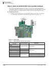
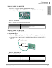
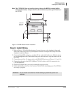
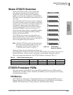
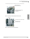
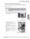
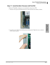
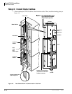
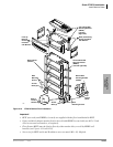
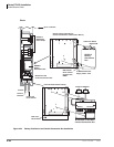
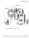
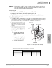
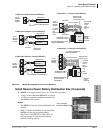
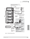
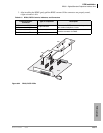
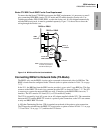
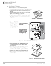
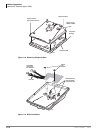
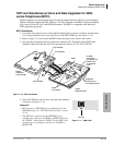
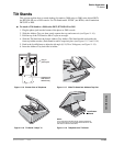
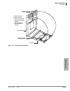
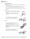
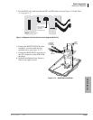
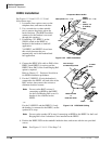
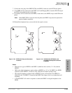
Install Processor and Universal PCBs
4-48 Strata CTX I&M 06/04
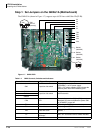
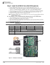
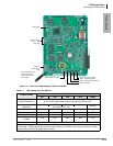
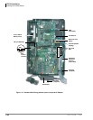
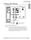
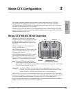
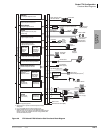
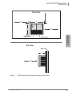
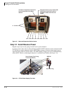
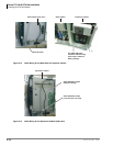
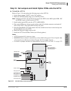
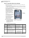
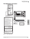
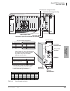
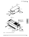
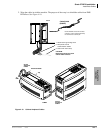
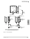
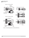
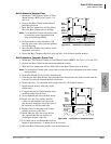
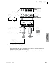
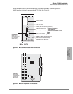
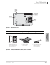
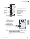
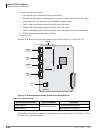
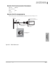
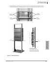
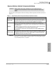
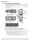
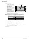
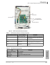
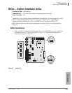
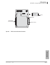
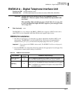
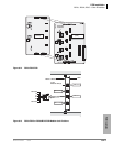
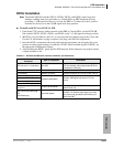
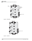
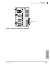
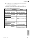
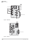
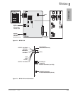
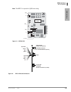
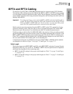
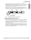
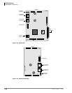
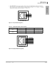
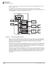
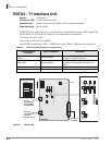
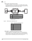
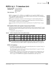
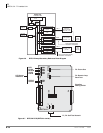
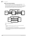
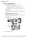
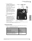
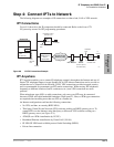
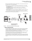
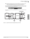
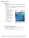
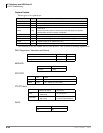
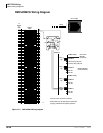
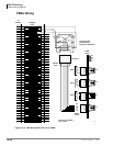
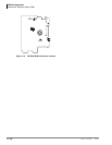
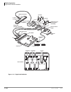
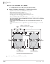
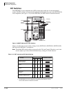
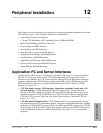
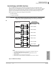
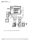
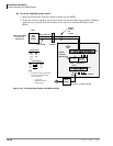
The following tables provide details about the connectors and indicators on the BCTU1A and
BEXU1A PCBs.
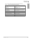
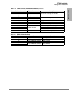
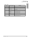
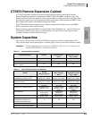
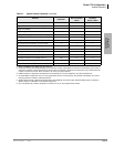
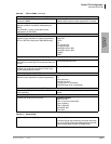
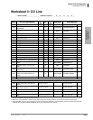
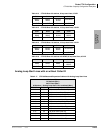
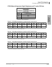
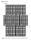
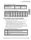
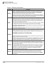
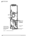
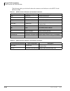
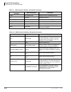
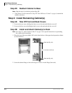
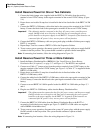
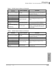
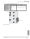
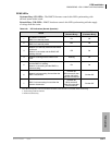
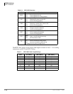
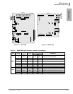
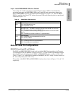
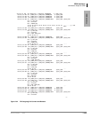
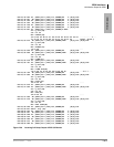
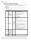
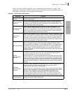
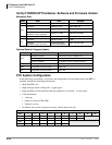
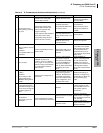
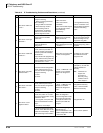
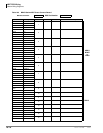
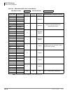
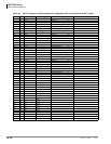
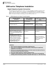
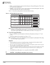
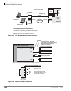
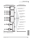
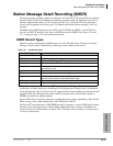
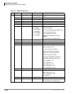
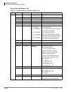
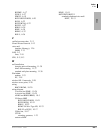
Table 4-9 BCTU Controls, Indicators, and Interface Connectors
Control/Indicator/Connector Type of Component Description
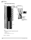
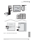
P801 RJ45 LAN Network interface port
P501 SmartMedia house SmartMedia Interface
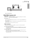
P802 RCA Jack BGM/MOH interface
P2, P3 44-pin connectors Processor backplane
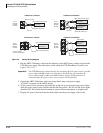
P601 BATT Jumper Plug
Must always be in the ON position to maintain
customer data.
LINK, TX, RX LED LAN link transmission and receive indicator
SM LED SmartMedia access indicator
HB LED Processor operation indication
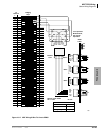
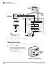
P7 60-pin connector AMDS interface (optional)
P8 60-pin connector BSIS interface (optional)
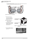
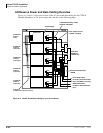
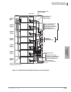
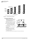
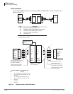
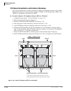
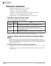
Connector P5 Connector and ribbon cable Ribbon cable connector to P4 (1) on the BEXU.
Connector P4 Connector and ribbon cable Ribbon cable connector to P5 (2) on the BEXU.
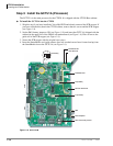
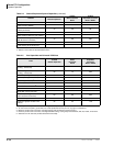
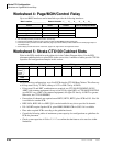
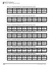
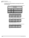
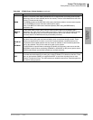
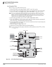
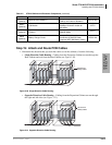
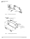
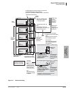
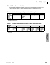
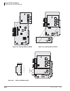
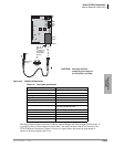
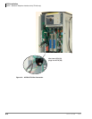
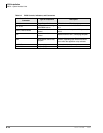
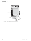
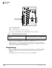
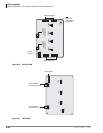
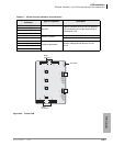
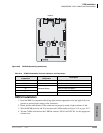
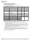
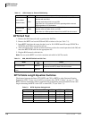
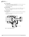
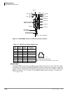
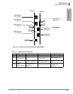
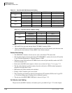
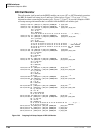
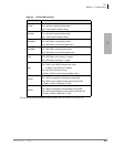
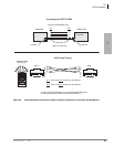
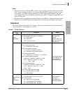
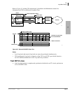
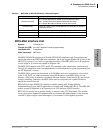
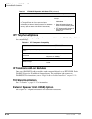
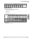
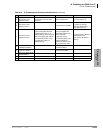
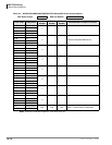
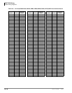
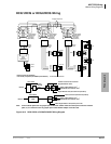
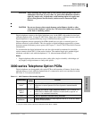
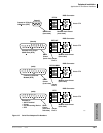
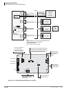
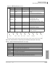
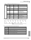
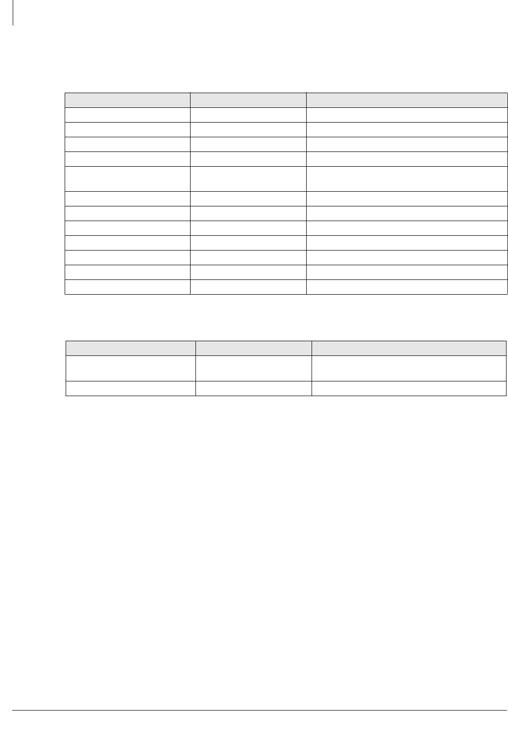
Table 4-10 BEXU Controls, Indicators, and Interface Connectors
Control/Indicator/Connector Type of Component Description
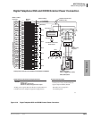
P901 BATT Jumper plug
Must
always
be in the ON position to maintain
customer data.
P4, P5 Connector and ribbon cable Ribbon cable connector to BCTU1A.