Strata CTX670 Installation
Install Power Supply
Strata CTX I&M 06/04 4-7
Strata CTX670
Installation
Note The backplane FG wires are not safety grounds: they are required for proper system CO line
operation.
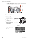
4. Plug the Back Plane DC OUT cable plug into the DC OUT connector on the power supply.
(The plug has a guide key on it to ensure that it is plugged in correctly.)
5. Secure the FG wire spade lug to the power supply with the FG screw.
6. Secure the power supply to the cabinet with the four provided screws.
7. If the cabinet is the Base Unit, a standalone Remote Expansion Cabinet, or the first in a stack of
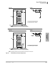
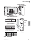
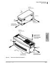
Remote Expansion Cabinets. Set the Exp/Base switch to the “Base” position (see Figure 4-3).
8. If the cabinet is an Expansion Unit, set the Exp/Base switch to the “Exp” position.
Important! The power supply set as “Base” is the master and has On/Off control over all other
power supplies, which are designated as slaves. If the master power supply is turned
Off or On, all other power supplies will automatically turn Off or On. (Individual
slave power supplies must be turned On.)
9. See Figure 4-3 to ensure that the power supply is properly installed.
10. Install power supplies in all cabinets, using Steps 1~9 of this procedure.
11. Install the Base and optional Expansion Cabinets, ground wiring, and cabinet bonding plates,
AC and reserve power cabling, and PCB cabling per the “Recommended Installation
Sequence” on page 4-6.
Check the -24 Volt Circuit Breakers
The BPSU672A provides four -24v circuit breakers as shown in Figure 4-3. If a low resistance
between –24 volts and ground exists the circuit breaker will trip. Usually the front panel DC green
LED indicator will turn off but not always. Also if AC power is recycled the DC LED indicator
may turn back on – even if the –24 volt circuit breaker is tripped.
Circuit Breaker Location and Slot Assignments (see Figure 4-3)
• The circuit breaker 24V1~24V4, located directly below DC-out cable, protects the cabinet slots
as shown in the Circuit Breaker assignment table.
Reset Circuit Breaker
1. A defective PCB or an external short on the MDF may cause the circuit breaker to trip.
2. If you suspect that a –24 volt circuit breaker has tripped, try to reset it by:
• Turn the power supply DC power switch off and unplug the power supply AC power cord
from the AC outlet – the inside of the power supply has exposed voltages.
• Gently press in each circuit breaker and listen for or try to feel it click. If the breaker was
tripped, you will hear or feel it click back to the set position.
• If the circuit breaker resets, pull the PCBs and check for MDF shorts associated with the
slots assigned to the tripped circuit breaker. Remove any defective PCBs and MDF shorts.
• Restore power and verify the system is working normally.
3. Replace the power supply if the circuit breaker continues to trip and a defective PCB or short
cannot be found.


