


ISDN Interfaces
BPTU and RPTU Cabling
Strata CTX I&M 06/04 7-11
ISDN Interfaces
BPTU and RPTU Cabling
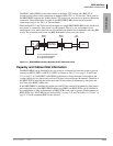
To meet Part 15 of FCC Rules, ISDN PRI equipment must be connected using CAT5, Shielded
Twisted-Pair (STP) cabling between the CSU and the BPTU or RPTU. CAT5 STP protects against
cross talk, Radio Frequency Interference (RFI), and/or Electro Magnetic Interference (EMI). STP
protects ISDN signal data while being transmitted through the cable and keeps the cable itself from
emitting EMI and RFI.
Important! To avoid ground loops, connect only the BPTU or RPTU end of the shielded cable to
ground. The Strata CTX grounds the CAT5 cable shield between the Strata CTX and
CSU at the BPTU or RPTU RJ45 jack. You do not have to connect the CSU ground
drain. The CSU ground should not be connected to the cable shield.
Shield continuity must be maintained from the BPTU or RPTU to the CSU, particularly if using
extension connecting cables. Keep the cable as short as possible between the CSU and the PRI
Demarcation jack, because there is no shield between the CSU and the Demarcation jack.
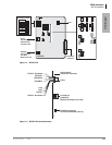
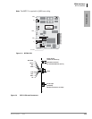
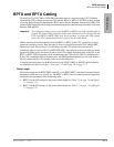
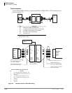
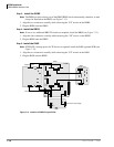
Toshiba provides a cable kit (Part No. RPRI-CBL-KIT), that contains all that you need to connect
the network ISDN jack to the network side of most CSUs and the equipment side of the CSU to the
BPTU or RPTU PCB. Depending on the manufacturer, the CSU may use DB15 or modular jacks.
If the CSU is equipped with the modular jacks, the DB15/modular adapters are not used. If this is
the case, make sure the CSU modular jacks are not shielded jacks.
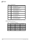
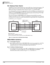
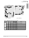
A detailed pinout diagram for the RJ45 network jack (USOC RJ48C or RJ48X) and the modular
cords/adaptors are shown in Figure 7-6 on page 7-12 and Figure 7-8 on page 7-13.
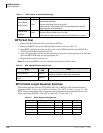
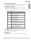
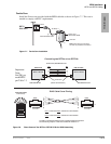
Cable Length
The distance between the BPTU/RPTU and CSU or the BPTU/RPTU and other Customer Premise
Equipment (CPE) may vary (0~655 ft.). The BPTU or RPTU must be equalized and its impedance
must match the impedance of the connecting cable.
³ BPTU: Set the SW settings for the proper cable length (see Table 7-3 on page 7-6 and Figure
7-3 on page 7-5).
³ RPTU: Set the SW settings for the proper cable length (see Table 7-7 on page 7-10 and Figure
7-5 on page 7-9).