


2 - 5
MDS-D2/DH2 Series Instruction Manual
2.2 Main Circuit Terminal Block/Control Circuit Connector
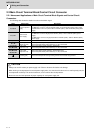
2.2.2 Connector Pin Assignment
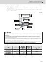
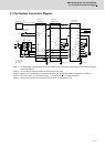
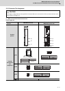
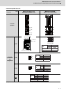
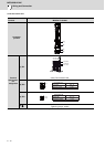
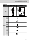
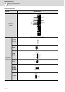
(1) Main circuit terminal block and connector
Power supply unit
(Note) The illustrations of drive units are shown as an example.
CAUTION
Do not apply a voltage other than that specified in Instruction Manual on each terminal. Failure to observe this item could
lead to rupture or damage, etc.
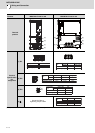
Unit
Terminal
MDS-D2-CV-37 to 75
MDS-D2-CV-110 to 185
MDS-DH2-CV-37 to 185
Terminal
position
Terminal
specification/
Pin
assignment
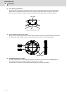
[1] TE1
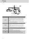
[2] TE2
[3] TE3
[4]
- The PE screw size is the same as TE1.
[2]
[3]
[
1
]
under
develop-
ment
[2]
[3]
[
4
]
[
1
]
1.2Nm
M4 x 12
U V W
Compatible unit
Screw size
Tightening torque
All of CV
(Note) This is a bottom view.
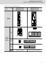
under
develop-
ment
under
development
2.0Nm
M5 x 12
U V W
Compatible unit
Screw size
Tightening torque
All of CV
4.0Nm
M6 x 16
L+
L-
Compatible unit
Screw size
Tightening torque
All of CV
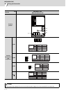
M4 × 12
1.2Nm
L11
L21
Compatible unit
Screw size
Tightening torque
All of CV