


5 - 45
MDS-D2/DH2 Series Instruction Manual
5.4 Adjustment during Full Closed Loop Control
5.4.2 Speed Loop Delay Compensation
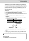
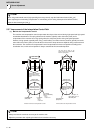
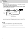
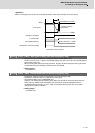
Generally, the machine position follows the operation later than the motor position. With full closed loop position loop
control, the machine position is used for position feedback, so the motor position could advance too far and cause the
machine position to overshoot easily. Speed loop delay compensation suppresses overshooting by weakening the speed
loop PI control (weakening lead compensation = delaying). If the compensation is too large and PI control is weakened
too far, the positioning time could increase, or the position droop will remain when the motor is stopped.
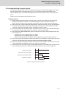
<Adjustment method>
[1] Set the servo function selection 1 (SV027: SSF1)/bit1, bit0 to 10. (Select delay compensation changeover type
2)
[2] Set the axis unbalance torque to the torque offset (SV032: TOF). (Refer to "Measuring unbalance torque and
frictional torque" for details on measuring the unbalance torque.)
[3] Observe the position droop waveform, and confirm the overshooting. Increase SV007 (VIL) in increments of 5,
and adjust so that the overshooting is improved. If set too high, the position droop will remain when the axis is
stopped.
【#2207】 SV007 VIL Speed loop delay compensation
Set this when the limit cycle occurs in the full-closed loop, or overshooting occurs in positioning.
The speed loop delay compensation method can be selected with SV027/bit1,0.
Normally, use "Changeover type 2". Changeover type 2 controls the occurrence of overshooting by
lowering the speed loop lead compensation after the position droop gets 0.
When setting this parameter, make sure to set the torque offset (SV032).
---Setting range---
0 to 32767
【#2232】 SV032 TOF Torque offset
Set the unbalance torque on vertical axis and inclined axis.
When the vertical axis pull up function is enabled, the pull up compensation direction is determined
by this parameter's sign. When set to "0", the vertical axis pull up will not be executed.
This can be used for speed loop delay compensation and collision detection function.
To use load inertia estimation function (drive monitor display), set this parameter, friction torque
(SV045) and load inertia display enabling flag(SV035/bitF).
---Setting range---
-100 to 100 (Stall current %)
【#2227】 SV027 SSF1 Servo function 1
bit 1-0 : vcnt Speed loop delay compensation changeover type selection
Normally, use "Changeover type 2".
bit1,0=
00: Disable
01: Changeover type 1
10: Changeover type 2
11: Setting prohibited
CAUTION
The position droop will remain if SV007 is set too high.