


4 Setup
MITSUBISHI CNC
4 - 2
4.1 Initial Setup
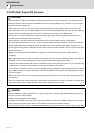
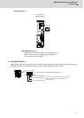
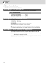
4.1.1 Setting the Rotary Switch
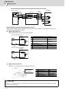
Before turning on the power, the axis No. must be set with the rotary switch. The rotary switch settings will be
validated when the drive units are turned ON.
< Drive unit >
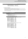
MDS-D2/DH2-V1/V2/SP, MDS-D2-V3/SP2 setting
Rotary switch setting AXIS NO.
01st axis
1 2nd axis
23rd axis
3 4th axis
4 5th axis
5 6th axis
6 7th axis
7 8th axis
8 9th axis
9 10th axis
A 11th axis
B 12th axis
C 13th axis
D 14th axis
E 15th axis
F 16th axis
(
'
%
&
$
#
(
'
%
&
$
#
(
'
%
&
$
#
(
'
%
&
$
#
(
'
%
&
$
#
(
'
%
&
$
#
(
'
%
&
$
#
(
'
%
&
$
#
(
'
%
&
$
#
3-axis
servo drive unit
(MDS-D2-V3)
L axis M axis
1-axis
spindle drive unit
(MDS-D2/DH2-SP)
2-axis
spindle drive unit
(MDS-D2-SP2)
1-axis
servo drive unit
(MDS-D2/DH2-V1)
2-axis
servo drive unit
(MDS-D2/DH2-V2)
L axis M axis S axis