


2 - 3
MDS-D2/DH2 Series Instruction Manual
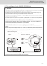
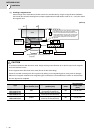
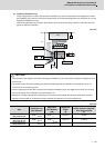
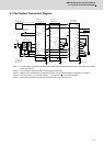
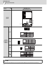
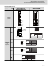
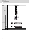
2.1 Part System Connection Diagram
2.1 Part System Connection Diagram
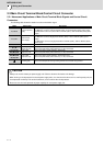
(Note 1) The total length of the optical communication cable from the NC must be within 30m and the minimum-bending
radius within 80mm.
(Note 2) The connection method will differ according to the used motor.
(Note 3) Battery for the encoder back up is built-in the drive unit. (An external battery is available as an option.)
(Note 4) The main circuit ( ◎ ) and control circuit ( ○ ) and ground ( ● ) are safely separated.
(Note 5) Connect the ground of the motor to the ground of the connected drive unit.
MC2
OPT1,2
T
S
R
CN1A
CN4
CN9
L1
L2
L3
L11
TE3
TE1
CN9
CN1B
L-
U
V
W
CN2
TE1
PLG
CN4
TE3
TE2
L+
L-
L11
L21
TE2
L21
CN3
CN1A
CN4
CN9
CN1B
MU
MV
MW
CN2L
CN2M
LU
LV
LW
TE1
TE3
TE2
L+
L-
L11
L21
CN3L
CN3M
MC
MC1
EMG1
EMG2
(PE)
(PE)
(PE)
(PE)
CN24
CN41
MDS-D2/DH2
MDS-D2/DH2
MDS-D2/DH2
CN23
CN8
CN5
CN8
CN20
CN5
Optical communication cable
24VDC
ۑ
: Control circuit
SH21
cable
AC
reactor
Machine side
encoder
Machine side
encoder
External emergency
stop input
Contactor
Ground
۔
: Main circuit
Spindle
motor
Motor side
encoder
Motor side
encoder
Servo
motor
Optical communication cable
Mitsubishi CNC
Spindle drive unitPower supply unit
Ground
Ground
Servo drive unit
Ground
Servo
motor
Circuit
protector
Circuit
protector
ە: Ground