


2 - 50
2 Wiring and Connection
MITSUBISHI CNC
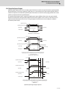
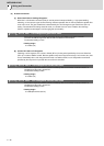
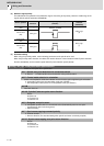
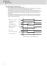
(3) Detection signal polarity
The table below is the polarities of the detections signals. According to the polarity, select the enable edge of the
signals with the spindle parameter (SP225/bit5).
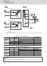
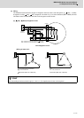
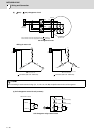
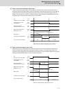
(4) Parameter setting
When using the proximity switch, set the following parameters to the spindle to be used.
When the proximity switch detection is enabled, the rotation direction of the orientation follows Z-phase detection
direction (#3106/bit0), and the rotation speed follows Z-phase detection speed (#3109).
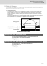
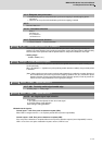
【#3106】 zrn_typ Zero point return specifications
Select the zero point return specification.
bit F : Spindle zero point detection with contactless switch
0: Normal 1: Enable spindle zero point detection using proximity switch
bit E : Control mode selection in orientation
Select non-interpolation mode when vibration occurs since the gain is high during the orientation.
0: Interpolation mode (Use the interpolation mode gain "SP002".)
1: Non-interpolation mode (Use the non-interpolation mode gain "SP001")
bit D-B :
Not used. Set to "0".
bit A-9 : Spindle/C axis zero point return direction
bitA,9=
00: Short-cut
01: Forward run
10: Reverse run
bit 8 : Designate zero point return
0: Compatible operation with our conventional series (Automatically return to zero point
simultaneously with C-axis changeover)
1: Standard setting
bit 7 : Synchronous tapping command polarity
0: Forward direction
1: Reverse direction (The standard setting when spindle and motor are directly coupled)
bit 6-5 : Synchronous tapping zero point return direction
bit 6,5=
00: Short-cut
01: Forward run
10: Reverse run
Sensor operation
Enable
detection
Drive unit input signal polarity
(CN9 DI1)
Enable edge
selection
(SP225/bit5)
Normal open
(NO)
Rising part
Falling edge
(0)
Normal close
(NC)
Falling part
Normal open
(NO)
Rising part
Rising edge
(1)
Normal close
(NC)
Falling part
Detection of enable
Detection of enable