


1 - 38
1 Installation
MITSUBISHI CNC
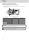
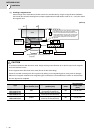
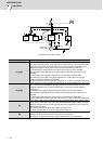
(1) Installing a magnetic drum
Install a flange on the shaft side and fix with screw in the axial direction by using the magnetic drum installation
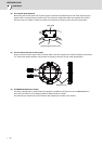
hole. Center the core with centering track so that the amplitude to the shaft rotation center is 15μm or less to install
the magnetic drum.
[Unit:mm]
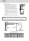
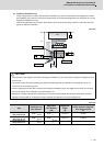
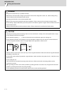
CAUTION
1. To avoid the interference with the sensor head, design the flange outer diameter φC so that it is equal to the magnetic
drum outer diameter or less.
2. Fix the magnetic drum with screw on the shaft. (Do not fix with shrink fitting.)
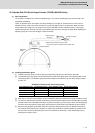
3. Center the core with centering track. Do not perform by striking on the magnetizing part as it may result in damages.
4. Adherence of magnetic materials to the magnetizing part could lead to incorrect detections. Perform an air blow when
the core alignment is completed.
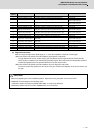
Type
Centering track
outer diameter [mm]
Magnetic drum installation hole
position [mm]
Installation
screw
Recommended
screw torque
[N•m]
MBA405W-BE082
MBE405W-BE082
φ98
8-φ3.4 through (evenly spaced
around φ90 circumference)
M3 0.61 to 0.83
MBA405W-BF125
MBE405W-BF125
φ148.3
8-φ4.5 through (evenly spaced
around φ134 circumference)
M4 1.39 to 1.89
MBA405W-BG160
MBE405W-BG160
φ198.6
8-φ4.5 through (evenly spaced
around φ170 circumference)
M5 2.75 to 3.63
A
A
A
Ǿ
C
Ǿ
B
0.01
0.015
R0..2
or less
Shaft
Flange
Centering track part
Iron-based screw
Magnetizing part
(magnet)
Magnetic drum
Magnetic drum
installation hole
Design the flange's outer diameter
Ǿ
B to have
the clearance (0.1 mm) from the magnetic
drum's inner diameter that allows the run-out
of the shaft rotation center to be 15mm or less.
*If the gap is large, adjustment may take time
and if it is too small, the run-out cannot be
adjusted.