


6 - 19
MDS-D2/DH2 Series Instruction Manual
6.1 Adjustment Procedures for Each Control
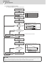
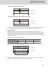
[3] Select "Synchronous tapping error measurement" on NC Analyzer, and perform synchronous tapping
operations with the operation pattern 2 above.
*The following measurement data of servo and spindle are automatically set when "Synchronous tapping error
measurement" is selected.
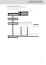
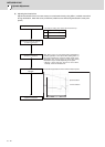
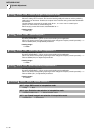
< NC Analyzer setting (Time-series data measurement) >
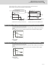
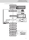
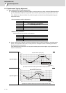
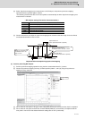
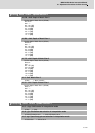
[4] Check the waveform and adjust the synchronous tapping time constant so that the margin for current limit at
acceleration/deceleration is 50% or more.
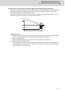
Output waveform example during synchronized tapping
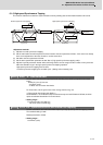
(2) Accuracy test using NC Analyzer
[1] Perform synchronous tapping operations using the time constant determined in (1) above.
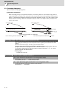
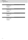
[2] Check the synchronous tapping accuracy (for both operation pattern 1 and 2) by using the synchronous
tapping accuracy check tool.
[3] If the number of error pulse is 100 (p-p) or less, satisfactory accuracy is secured, and the check is completed.
[4] If the number of error pulse exceeds 100, increase SP008 (VGN2) by 10 increments, and adjust so that the
error pulse is 100 or less. Note that the maximum setting value is 150 × [inertia ratio].
Get Waveform type
CH1 Synchronous tapping error *Position error of spindle and servo axis
CH2 Speed feed back of servo
CH3 Speed feed back of spindle
CH4 Current feed back of servo
CH5 Current feed back of spindle
0
0
3000r/min
Current limit level
Current limit level
Margin for current limit at
acceleration has to be
50% or more.
Margin for current limit at
deceleration has to be 50% or more.
Speed feed back
(CH3: Speed feed back of spindle)
Current feed back
(CH5: Current feed back of spindle)
Error pulse display