


7 - 9
MDS-D2/DH2 Series Instruction Manual
7.2 Protective Functions List of Units
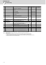
7.2.2 List of Warnings
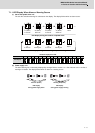
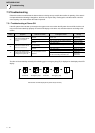
When a warning occurs, a warning No. will appear on the NC monitor screen and with the LEDs on the front of the drive
unit. Check the warning No., and remove the cause of the warning by following this list.
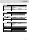
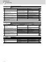
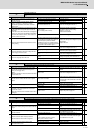
(1) Drive unit warning
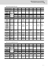
(Note1) Definitions of terms in the table are as follows.
Main side encoder: Encoder connected to CN2 Sub side encoder: Encoder connected to CN3
(Note 2) Resetting methods
* : Automatically reset once the cause of the warning is removed.
NR: Reset with the NC RESET button. This warning can also be reset with the PR and AR resetting conditions.
PR: Reset by turning the NC power ON again. This warning can also be reset with the AR resetting conditions.
When the control axis is removed, this warning can be reset with the NC RESET button. (Excluding warning 93.)
AR: Reset by turning the servo drive unit power ON again.
(Note 3) Servo and spindle motor do not stop when the warning occurs.
(Note 4) When an emergency stop is input, servo and spindle motor decelerate to a stop.
(When SV048, SV055 or SV056 is set for servo and when SP055 or SP056 is set for spindle.)
(Note 5) When using MDS-BTBOX-36, the reset method is AR.
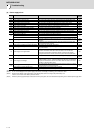
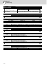
(2) Power supply warning
(Note 1) Resetting methods
* : Automatically reset once the cause of the warning is removed.
NR: Reset with the NC RESET button. This warning can also be reset with the PR and AR resetting conditions.
PR: Reset by turning the NC power ON again. This warning can also be reset with the AR resetting conditions.
When the control axis is removed, this warning can be reset with the NC RESET button. (Excluding warning 93.)
AR: Reset by turning the servo drive unit power ON again.
(Note 2) Servo and spindle motor do not stop when the warning occurs.
(Note 3) Check the LED display of the power backup unit to identify what warning is occurring to the power backup unit.
**Refer to "9.5.3 List of Power Backup Function Warnings".
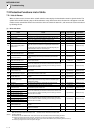
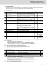
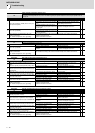
No. Name Details
Reset
method
Stop method
96 Scale feedback error
An excessive difference in feedback amount was detected between the
main side encoder and the MPI scale in MPI scale absolute position
detection system.
*-
97 Scale offset error
An error was detected in the offset data that is read at the NC power-
ON in MPI scale absolute position detection system.
PR -
9B
Incremental encoder/
magnetic pole shift warning
The difference between the magnetic pole position after the phase Z
has been passed (magnetic pole shift amount:SV028) and the initially
detected position is excessive in the built-in motor's incremental control
system.The magnetic pole is controlled by the initial detection value.
*-
9E
Absolute position encoder: Revolution
counter error
An error was detected in the revolution counter data of the absolute
position encoder. The accuracy of absolute position is not guaranteed.
*-
9F Battery voltage drop
The battery voltage to be supplied to the absolute position encoder is
dropping.
NR
(Note 5)
-
A3 In initial setup of ABS position
This warning is detected until the axis reaches the reference position
during the initial setup of the distance-coded reference check function.
This warning turns OFF after the axis has reached the position, thus set
the value displayed on the drive monitor to the parameter.
This warning is detected during the initial setup of MBA405W.
This warning turns OFF after the initial setup is completed by having
the axis pass the Z-phase of MBA405W and turning the NC power ON
again.
PR -
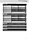
A4 Dual signal warning An input was detected in the signal related to the dual signal. * -
A6 Fan stop warning A cooling fan in the drive unit stopped. * -
E0 Overregeneration warning Over-regeneration detection level exceeded 80%. * -
E1 Overload warning A level of 80% of the Overload 1 alarm state was detected. * -
E4 Parameter warning
An incorrect set value was detected among the parameters send from
the NC in the normal operation.
*-
E6 Control axis detachment warning A control axis is being detached. (State display) * -
E7 NC emergency stop In NC emergency stop. (State display) *
Deceleration stop
enabled
E8
to
EF
Power supply warning
The power supply unit detected a warning. The error details are
different according to the connected power supply unit.
Refer to "Power supply warning".
*
-
*EA:
Deceleration stop
enabled
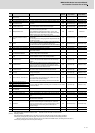
No. Name Details
Reset
method
E9 Instantaneous power interruption warning The power was momentarily interrupted. NR
EA In external emergency stop state External emergency stop signal was input. *
EB Power supply: Over regeneration warning Over-regeneration detection level exceeded 80%. *
EE Power supply: Fan stop warning A cooling fan built in the power supply unit stopped. *
EF Power supply: Option unit warning A warning was detected in the power backup unit (power supply option unit). * (Note 3)