


2 - 41
MDS-D2/DH2 Series Instruction Manual
2.8 Peripheral Control Wiring
2.8 Peripheral Control Wiring
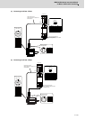
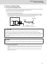
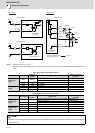
2.8.1 Input/Output Circuit Wiring
CN9 connector is equipped with 24V input/output circuit for the control of external devices and the control by an external
signal.
Set the relevant parameters and use them with care for the wiring since some signals are changeover type, which can be
switched over by parameters. Refer to the description of each function in relevant sections for details on the function
specifications and settings.
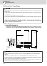
For a switch or relay to be wired, use a switch or relay that satisfies the input/output (voltage, current) conditions.
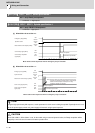
Connector Input condition Connector Output condition
CN9
Switch ON
18VDC to 25.2VDC
4.3mA or more
CN9
Output voltage 24VDC ±5%
Switch OFF
4VDC or less
2mA or less
Tolerable output
current to
50mA or less
CN24
Switch ON
18VDC to 25.2VDC
4.3mA or more
Switch OFF
4VDC or less
2mA or less
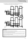
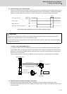
Interface name Selection example
For digital input signal (CN24,CN9)
Use a minute signal switch which is stably contacted and operated even with low
voltage or current.
< Example > OMRON: G2A, G6B type, MY type, LY type
For digital output signal (CN9)
Use a compact relay operated with rating of 24VDC, 50mA or less.
< Example > OMROM: G6B type, MY type