


Outline for MDS-D2/DH2 Series
Specifications Manual (IB-1501124-B)
1 Introduction
1.1 Servo/Spindle Drive System Configuration
1.1.1 System Configuration
1.2 Explanation of Type
1.2.1 Servo Motor Type
1.2.2 Servo Drive Unit Type
1.2.3 Spindle Motor Type
1.2.4 Tool Spindle Motor Type
1.2.5 Spindle Drive Unit Type
1.2.6 Power Supply Unit Type
1.2.7 AC Reactor Type
2 Specifications
2.1 Servo Motor
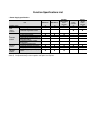
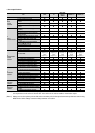
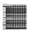
2.1.1 Specifications List
2.1.2 Torque Characteristics
2.2 Spindle Motor
2.2.1 Specifications
2.2.2 Output Characteristics
2.3 Tool Spindle Motor
2.3.1 Specifications
2.3.2 Output Characteristics
2.4 Drive Unit
2.4.1 Installation Environment Conditions
2.4.2 Servo Drive Unit
2.4.3 Spindle Drive Unit
2.4.4 Power Supply Unit
2.4.5 Unit Outline Dimension Drawing
2.4.6 AC Reactor
2.4.7 Explanation of Each Part
3 Function Specifications
Function Specifications List
3.1 Base Control Functions
3.1.1 Full Closed Loop Control
3.1.2 Position Command Synchronous Control
3.1.3 Speed Command Synchronous Control
3.1.4 Distance-coded Reference Position Control
3.1.5 Spindle's Continuous Position Loop Control
3.1.6 Coil Changeover Control
3.1.7 Gear Changeover Control
3.1.8 Orientation Control
3.1.9 Indexing Control
3.1.10 Synchronous Tapping Control
3.1.11 Spindle Synchronous Control
3.1.12 Spindle/C Axis Control
3.1.13 Proximity Switch Orientation Control
3.1.14 Power Regeneration Control
3.1.15 Resistor Regeneration Control
3.2 Servo/Spindle Control Functions
3.2.1 Torque Limit Function
3.2.2 Variable Speed Loop Gain Control
3.2.3 Gain Changeover for Synchronous Tapping
Control
3.2.4 Speed Loop PID Changeover Control
3.2.5 Disturbance Torque Observer
3.2.6 Smooth High Gain Control (SHG Control)
3.2.7 High-speed Synchronous Tapping Control
(OMR-DD Control)
3.2.8 Dual Feedback Control
3.2.9 HAS Control
3.2.10 OMR-FF Control
3.2.11 Control Loop Gain Changeover
3.2.12 Spindle Output Stabilizing Control
3.2.13 High-response Spindle Acceleration/De-
celeration Function
3.3 Compensation Control Function
3.3.1 Jitter Compensation
3.3.2 Notch Filter
3.3.3 Adaptive Tracking-type Notch Filter
3.3.4 Overshooting Compensation
3.3.5 Machine End Compensation Control
3.3.6 Lost Motion Compensation Type 2
3.3.7 Lost Motion Compensation Type 3
3.3.8 Lost Motion Compensation Type 4
3.3.9 Spindle Motor Temperature Compensation
Function
3.4 Protection Function
3.4.1 Deceleration Control at Emergency Stop
3.4.2 Vertical Axis Drop Prevention/Pull-up Con-
trol
3.4.3 Earth Fault Detection
3.4.4 Collision Detection Function
3.4.5 SLS (Safely Limited Speed) Function
3.4.6 Fan Stop Detection
3.4.7 Open-phase Detection
3.4.8 Contactor Weld Detection
3.4.9 STO (Safe Torque Off) Function
3.4.10 Deceleration and Stop Function at Power
Failure
3.4.11 Retraction Function at Power Failure
3.5 Sequence Functions
3.5.1 Contactor Control Function
3.5.2 Motor Brake Control Function
3.5.3 External Emergency Stop Function
3.5.4 Specified Speed Output
3.5.5 Quick READY ON Sequence
3.6 Diagnosis Function
3.6.1 Monitor Output Function
3.6.2 Machine Resonance Frequency Display
Function
3.6.3 Machine Inertia Display Function
3.6.4 Motor Temperature Display Function
3.6.5 Load Monitor Output Function
3.6.6 Open Loop Control Function
3.6.7 Power Supply Diagnosis Display Function
4 Characteristics
4.1 Servo Motor
4.1.1 Environmental Conditions
4.1.2 Quakeproof Level
4.1.3 Shaft Characteristics
4.1.4 Machine Accuracy
4.1.5 Oil / Water Standards
4.1.6 Installation of Servo Motor
4.1.7 Overload Protection Characteristics
4.1.8 Magnetic Brake