


5 - 28
5 Servo Adjustment
MITSUBISHI CNC
5.3.3 Improving the Cutting Surface Precision
If the cutting surface precision or roundness is poor, these can be improved by increasing the speed loop gain (VGN1,
VIA) or by using the disturbance observer function.
<Examples of faults>
• The surface precision in the 45° direction of a taper or arc is poor.
• The load fluctuation during cutting is large, causing vibration or surface precision defects to occur.
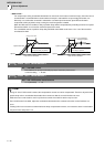
(1) Adjusting the speed loop gain (VGN1)
If the speed loop gain is increased, the cutting surface precision will be improved but the machine will resonate
easily.
The final VGN1 setting should be approx. 70 to 80% of the maximum value where resonance does not occur. (Refer
to "Setting the speed loop gain")
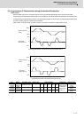
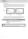
(2) Adjusting the speed loop leading compensation (VIA)
The VIA has a large influence on the position trackability, particularly during high-speed cutting (generally F1000 or
more). Raising the setting value improves the position trackability, and the contour precision during high-speed
cutting can be improved. For high-speed high-precision cutting machines, adjust so that a value equal to or higher
than the standard value can be set.
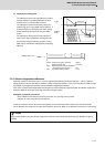
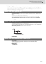
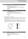
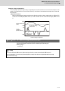
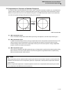
When VIA is set lower than the standard value and set to a value differing between interpolation axes, the
roundness may worsen (the circle may distort). This is due to differences occurring in the position trackability
between interpolation axes. The distortion can be improved by matching the VIA with the smaller of the values. Note
that because the position trackability is not improved, the surface precision will not be improved.
(Refer to "Setting the speed loop lead compensation")
POINT
Adjust by raising the speed loop gain equivalently to improve cutting surface precision, even if the measures differ. In this
case, it is important how much the machine resonance can be controlled, so adjust making sufficient use of vibration
suppression functions.
X
Y