


6 - 38
6 Spindle Adjustment
MITSUBISHI CNC
6.3 Spindle Control Signal
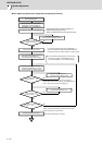
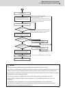
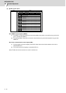
The sequence input/output signals exchanged between the NC and spindle drive unit are explained in this section. The
status of each signal is displayed on the NC SPINDLE MONITOR screen.
6.3.1 Spindle Control Input (NC to Spindle)
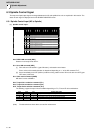
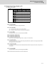
(1) Spindle control input 1
bit0. READY ON command (RDY)
Status turns to ready ON at RDY=1.
bit1. Servo ON command (SRV)
[1] Drive unit turns ON at SRV=1 (gate ON status), and rotation control starts.
Plus or minus of the rotation direction is determined depending on +/- of the NC command FΔT.
[2] Servo immediately turns OFF (SON=0) at SRV=0 during rotation control. Drive unit also turns OFF (gate
OFF status) at this time.
bit7. Alarm reset command (ALMR)
NR alarm is reset at ALMR=1.
bit8. Torque limit 1 selection command (TL1)
bit9. Torque limit 2 selection command (TL2)
bitA. Torque limit 3 selection command (TL3)
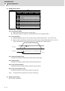
The following 4 types of torque limit are available depending on TL1, TL2 and TL3 bit combinations.
(Note) The ratio to motor short time rated torque (load meter 100%) is indicated in %.
(Note) The bits other than those above are used for maintenance.
TL3 TL2 TL1 Torque limit value
0 0 1 Torque limit value (%) set with parameter SP065
0 1 0 Torque limit value (%) set with parameter SP066
0 1 1 Torque limit value (%) set with parameter SP067
1 0 0 Torque limit value (%) set with parameter SP068
Name Details
Spindle control input 1
F E D C B A 9 8 7 6 5 4 3 2 1 0
TL3 TL2 TL1
ALMR
SRV RDY
bit Details
0
RDY
READY ON command
1
SRV
Servo ON command
2
- (For maintenance)
3
-
(For maintenance)
4
-
(For maintenance)
5
-
(For maintenance)
6
-
(For maintenance)
7
ALMR
Alarm reset command
8
TL1
Torque limit 1 selection command
9
TL2
Torque limit 2 selection command
A
TL3
Torque limit 3 selection command
B
-
(For maintenance)
C
-
(For maintenance)
D
-
(For maintenance)
E
-
(For maintenance)
F
-
(For maintenance)