


Appendix 2 Cable and Connector Assembly
MITSUBISHI CNC
Appendix 2 - 2
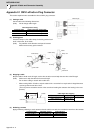
Appendix 2.1 CMV1-xPxxS-xx Plug Connector
This section explains how to assemble the wire to CMV1 plug connector.
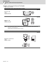
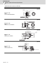
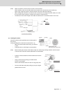
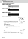
(1) Cutting a cable
Cut the cable to the following dimensions:
(Note) Not to change cable length.
Cable length after cutting
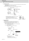
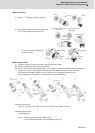
(2) Inserting parts
Insert the clamp nut, the cable clamp, the bushing and the back
shell, in that order, to the cable.
(Note) Pay attention to the direction each part is inserted.
Make sure that every part is inserted.
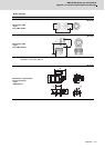
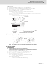
(3) Stripping a cable
Strip the cable’s sheath to the A length, cut the wire set at its root and strip the core wire to the B length.
(Note) Make sure to strip the cable to the correct length.
Do not leave cutting or scratch to the cable core.
* When making CMV1-xP10S-xx, strip the cable for No. 10 terminal in a way that the A length becomes
1mm longer than that of other cores.
(This is to prevent excessive tension of the core when inserting the contact to the housing in the next
process.)
Cable length after stripping
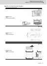
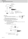
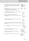
(4) Soldering a contact
Apply preliminary soldering to each contact and to the cable’s core wire, then solder the core wire to the contacts.
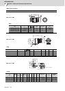
connector name Cable length after cutting [mm]
CMV1-SPxxS-xx 40±0.5 + Cable length
CMV1-APxxS-xx 47±0.5 + Cable length
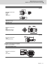
Connector name A [mm] B [mm]
CMV1-SPxxS-xx 21.5 to22.5
4.5 to 5.0
CMV1-APxxS-xx 28.5to 29.5
Connector name Applicable contact Applicable wire
CMV1-xP2S-xx CMV1-#22BSC-S2 AWG16 or below
CMV1-xP10S-xx CMV1-#22ASC-S1 AWG20 or below
Cable length
Cable length
Back shell
Cable
Cable
Cable clamp
Cable clamp
Clamp nut
Clamp nut
Angle
back shell
Bushing
Bushing
A
B
Sheath
Core wire
(A+1mm for No. 10 terminal
only)
Cable core