


1 - 19
MDS-D2/DH2 Series Instruction Manual
1.3 Installation of Tool Spindle Motor
1.3 Installation of Tool Spindle Motor
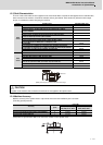
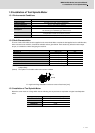
1.3.1 Environmental Conditions
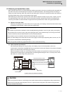
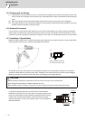
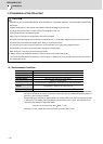
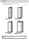
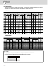
1.3.2 Shaft Characteristics
There is a limit to the load that can be applied on the motor shaft. Make sure that the load applied on the radial direction,
when mounted on the machine, is below the tolerable values given below. These loads may affect the motor output
torque, so consider them when designing the machine.
(Note 1) The tolerable radial load and thrust load in the above table are values applied when each motor is used
independently.
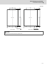
(Note 2) The symbol L in the table refers to the value of L below.
L: Length from flange installation surface to center of load mass [mm]
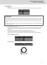
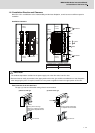
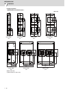
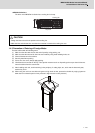
1.3.3 Installation of Tool Spindle Motor
Mount the servo motor on a flange which has the following size or produces an equivalent or higher heat dissipation
effect:
Environment Conditions
Ambient temperature 0°C to +40°C (with no freezing)
Ambient humidity 80% RH or less (with no dew condensation)
Storage temperature -15°C to +70°C (with no freezing)
Storage humidity 90% RH or less (with no dew condensation)
Atmosphere
Indoors (no direct sunlight)
No corrosive gas, inflammable gas, oil mist or dust
Altitude
Operation/storage: 1000m or less above sea level
Transportation: 10000m or less above sea level
Vibration
X:19.6m/s
2
(2G) Y:19.6m/s
2
(2G)
Tool spindle motor Tolerable radial load Tolerable thrust load
HF-KP46, 56 245N (L=30) 98N
HF-KP96 392N (L=40) 147N
HF-SP226, 406 980N(L-55 490N
HF75S, 105S 245N (L=33) 147N
HF54S, 104S, 154S, 224S 980N (L=55) 490N
HF204S, 354S,453S,703S 2058N (L=79) 980N
HF903S 2450(L=85) 980N
Flange size (mm) Tool spindle motor capacity
250×250×6 400W
250×250×12 0.5 to 1.5kW
300×300×20 2.0 to 3.0kW
800×800×35 9.0kW
Radial load
Thrust load
L