


Appendix 1 - 5
MDS-D2/DH2 Series Instruction Manual
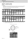
Appendix 1.2 Cable Connection Diagram
Appendix 1.2 Cable Connection Diagram
Appendix 1.2.1 Battery Cable
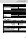
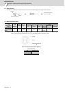
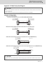
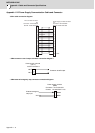
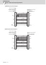
< DG21 cable connection diagram
(Connection cable between drive unit and A6BAT (MR-BAT) (MDS-BTCASE) >
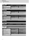
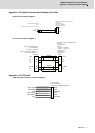
<DG22 cable connection diagram (Connection cable between drive unit and drive unit)>
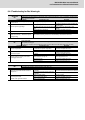
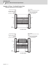
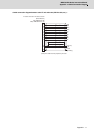
< DG23 cable connection diagram (Connection cable between drive unit and MDS-BTBOX-36) >
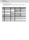
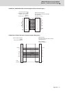
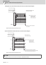
< DG24 cable connection diagram (Connection cable for alarm output between drive unit and MDS-BTBOX-36) >
CAUTION
1. Take care not to mistake the connection when manufacturing the encoder cable. Failure to observe this could lead to
faults, runaway or fire.
2. When manufacturing the cable, do not connect anything to pins which have no description.
CAUTION
When DG24 cable is used, proximity switch or external emergency stop cannot be wired, so these functions cannot be
used.
1
2
9
1
PE
BT
LG
BT
LG
0.2mm
2
Drive unit side connector
Connector: DF1B-2S-2.5R
Contact: DF1B-2428SCA
Battery unit side connector
Connector: 10120-3000VE
Shell kit: 10320-52F0-008
Case
grounding
(Hirose Electric)
(3M)
1
2
1
2
BT
LG
BT
LG
0.2mm
2
Drive unit side connector
Connector: DF1B-2S-2.5R
Contact: DF1B-2428SCA
Drive unit side connector
Connector: DF1B-2S-2.5R
Contact: DF1B-2428SCA
(Hirose Electric)
(Hirose Electric)
1
2
BT
LG
BT
LG
0.2mm
2
: DF1B-2S-2.5R
: DF1B-2428SCA
Battery box side
Drive unit side connector
Connector
Contact
(Hirose Electric)
20
13
4
1
FG
DICOM
D11
P5
LG
24G
DOCOM
+5V
LG
0.2mm
2
:10120-3000VE
:10320-52F0-008
0.2mm
2
0.2mm
2
Case
grounding
Drive unit side connector
Connector
Shell kit
Battery box side
(3M)
Blue
Light blue
Yellow
White