


2 - 36
2 Wiring and Connection
MITSUBISHI CNC
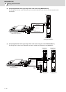
2.6.2 Connecting the Grounding Cable
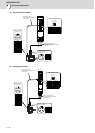
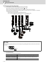
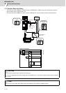
(1) Connecting the protective grounding (PE) and frame ground (FG)
Each unit has a terminal or mounting hole to connect PE ( ) or FG.
Please connect an earth wire to the main ground of a cabinet or a machine frame at one point.
Ground each device according to the grounding conditions set forth by each country. (Typically, a Y-connection
neutral point ground is used in Europe.)
PE: Grounding to provide protection from electric shock, etc.
FG: Grounding to stabilize the operation of the devices, etc. (Suppress noise)
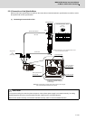
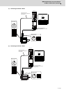
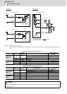
(2) Grounding cable size
Earth wire size should follow the following table.
POINT
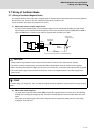
Do not connect the grounding cable from each unit directly to the grounding plate. Noise from other units could result in
malfunctions.
Type Grounding cable size (Required grounding)
MDS-D2/DH2-CV Unit Larger than thickness of wire connected to TE1 (L1/L2/L3). (PE)
MDS-D2/DH2-V1/V2/V3/SP/SP2 Unit
Larger than thickness of wire connected to TE1 (U/V/W). (PE)
(For two or three axes, the thickness of wire which the total current can be
applied to.)
D/DH-AL (AC Reactor)
5.5 mm
2
(AWG10) or more (FG)
MDS-D2/DH2-V1/V2//V3/SP/SP2 MDS-D2/DH2-CV
D/DH-AL
Spindle motor
Servo motor
Grounding plate
Grounding
plate
Unit