


7 - 17
MDS-D2/DH2 Series Instruction Manual
7.3 Troubleshooting
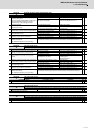
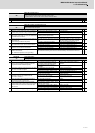
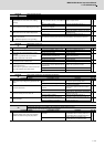
Alarm No.
2E
Main side encoder: Error 4
The motor side encoder (CN2 side) detected an error.
(Note) It includes the linear scale in the case of linear motor.
As details differ for each encoder, refer to section "Encoder alarm".
Investigation details Investigation results Remedies SV SP
1 Check the alarm No. "1B" items.
◯◯
Alarm No.
2F
Main side encoder: Communication error
An error was detected in communication data with the motor side encoder or with the linear scale of a linear servo system. Or the
communication was interrupted.
Investigation details Investigation results Remedies SV SP
1
Jiggle the encoder connectors (drive unit side and
encoder side) and check if they are disconnected.
The connector is disconnected (or loose). Correctly install.
◯◯
The connector is not disconnected. Check the investigation item No. 2.
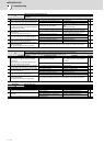
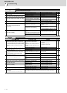
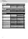
2
Is the encoder cable wired in the same conduit as
the motor's power cable, or are the two cables laid
in parallel near each other?
The cables are wired near each other. (Noise
is entering from the power cable.)
Improve the cable wiring.
◯◯
The wires are sufficiently separated. Check the investigation item No. 3.
3
Is the motor FG wire connected only to the drive unit
which drives it?
(Is the motor grounded to one point?)
The motor FG wire is grounded on the motor
side.
Ground the motor to one point, connecting
the wires together on the drive unit side.
◯◯
The motor is grounded to one point. Check the investigation item No. 4.
4
Turn the power OFF, and check the encoder cable
connection with a tester. (Is the cable shielded?)
The connection is faulty. Replace the encoder cable.
◯◯
The connection is normal. Check the investigation item No. 5.
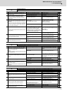
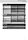
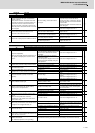
5
Replace with another unit, and check whether the
fault is on the unit side or encoder side.
The alarm is on the drive unit side. Replace the drive unit.
◯◯
The alarm is on the encoder side. Check the investigation item No. 6.
6
Check if there is any abnormality in the encoder's
ambient environment.
(Ex. Ambient temperature, noise, grounding)
Take remedies according to the causes of the abnormality in the ambient environment.
◯◯
Alarm No.
30
Over regeneration:
Over-regeneration detection level became over 100%. The regenerative resistor is overloaded.
Investigation details Investigation results Remedies SV SP
1
Check if the regenerative capacity exceeds the
regenerative resistor tolerable capacity.
The regenerative capacity exceeds the
regenerative resistor tolerable capacity.
Add the option regenerative resistor or
replace it.
◯◯
The regenerative resistor selection is
appropriate.
Check the investigation item No. 2.
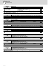
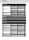
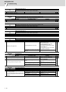
2
Check if the parameter is set incorrectly, and check
the values of sv036 and sp032.
The parameters are set incorrectly. Change the parameters.
◯◯
The parameters are correct. Check the investigation item No. 3.
3 Is an external regenerative resistor used?
An external regenerative resistor is used. Check the investigation item No. 5.
◯
A built-in regenerative resistor is used. Check the investigation item No. 4.
4
Is the short wire connected between P and D
terminal? Are there any problems with the
connection condition?
The wire is not connected. Connect the wire.
◯
The connector is disconnected.
The connector has a contact fault.
Reconnect the connector.
Replace the connector.
5
Is the connection of the regenerative resistor or
regeneration resistor cable correct?
The connection is incorrect. Rewire.
◯◯
The connection is correct. Check the investigation item No. 6.
6
Is the regeneration resistor or the regeneration
resistor cable broken? Disconnect the regenerative
resistor terminal and check the resistance value
with a tester.
The regeneration resistor is broken. Or the
resistance value is large.
Replace the regenerative resistor.
◯◯
The regeneration resistor cable is broken. Replace the cable.
The resistance value is normal. Check the investigation item No. 7.
7 Check if the power supply voltage is too high.
The power supply voltage exceeded 253V. Review the power supply.
◯◯
The power supply voltage is normal. Replace the drive unit.