


5 - 29
MDS-D2/DH2 Series Instruction Manual
5.3 Characteristics Improvement
【#2205】 SV005 VGN1 Speed loop gain 1
Set the speed loop gain.
The higher the setting value is, the more accurate the control will be, however, vibration tends to
occur.
If vibration occurs, adjust by lowering by 20 to 30%.
The value should be determined to the 70 to 80% of the value at which the vibration stops.
The value differs depending on servo motors.
Aim at the standard value determined by the servo motor type and load inertia ratio to adjust.
---Setting range---
1 to 30000
【#2208】 SV008 VIA Speed loop lead compensation
Set the gain of the speed loop integral control.
Standard setting: 1364
Standard setting in the SHG control: 1900
Adjust the value by increasing/decreasing this by about 100 at a time.
Raise this value to improve contour tracking accuracy in high-speed cutting.
Lower this value when the position droop does not stabilize (when the vibration of 10 to 20Hz
occurs).
---Setting range---
1 to 9999
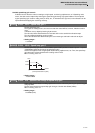
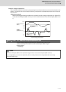
(3) Voltage non-sensitive zone (Td) compensation
With the PWM control of the inverter circuit, a dead time (non-energized time) is set to prevent short-circuits caused
by simultaneous energizing of the P side and N side transistors having the same phase. The dead time has a non-
sensitive zone for particularly low voltage commands. Thus, when feeding with a low speed and a low torque, the
control may be unstable.
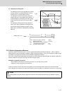
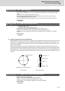
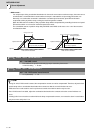
When an unbalanced axis is lowering, the frictional torque and unbalance torque, and the frictional torque and
deceleration torque before the quadrant changes during circle cutting, are balanced. The motor output torque will be
approximately zero, and the control accuracy may drop. In this case, the control accuracy can be improved by using
the voltage non-sensitive band compensation. Note that this may cause vibration to be increased while the motor is
running.
【#2230】 SV030 IVC Voltage non-sensitive band compensation
When 100% is set, the voltage reduction amount equivalent to the logical non-energization in the
PWM control will be compensated.
When "0" is set, 100% compensation will be performed.
Adjust in increments of 10% from the default value of 100%.
If increased too much, vibration or vibration noise may be generated.
---Setting range---
0 to 255 (%)
Frictional tor
q
ue
Lowering
Balanced
Unbalance torque
For unbalance torque
For circle cutting
Cutting direction
Deceleration torque = frictional torque
Motor torque Ҹ 0