


1 - 6
1 Installation
MITSUBISHI CNC
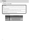
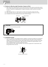
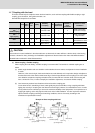
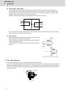
1.1.6 Machine Accuracy
Machine accuracy of the servo motor's output shaft and around the installation part is as below.
(Excluding special products)
CAUTION
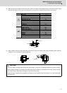
1. Use a flexible coupling when connecting with a ball screw, etc., and keep the shaft core deviation to below the tolerable
radial load of the shaft.
2. When directly installing the gear on the motor shaft, the radial load increases as the diameter of the gear decreases. This
should be carefully considered when designing the machine.
3. When directly installing the pulley on the motor shaft, carefully consider so that the radial load (double the tension)
generated from the timing belt tension is less than the values shown in the table above.
4. In machines where thrust loads such as a worm gear are applied, carefully consider providing separate bearings, etc., on
the machine side so that loads exceeding the tolerable thrust loads are not applied to the motor.
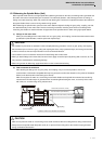
Accuracy
Measurement
point
Flange size [mm]
Less than 100 SQ. 100 SQ., 130 SQ. 176 SQ. - 250 SQ. 280 SQ. or over
Run-out of the flange surface to
the output shaft
a 0.05mm 0.06mm 0.08mm 0.08mm
Run-out of the flange surface's
fitting outer diameter
b 0.04mm 0.04mm 0.06mm 0.08mm
Run-out of the output shaft end c 0.02mm 0.02mm 0.03mm 0.03mm
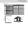
a c
b