


Appendix 7 - 4
Appendix 7 Higher Harmonic Suppression Measure Guidelines
MITSUBISHI CNC
(2) Calculating the higher harmonic current flow (Step 2)
To calculate the higher harmonic current flow, calculate the rated current for the incoming power voltage
conversion.
Rated current for incoming power voltage conversion (mA) = a • Pi
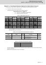
(Table 4) Incoming power voltage conversion coefficient a
(Table 5) Upper limit of higher harmonic current flow (mA/kW)
Obtain the upper limit of the higher harmonic current flow (judgment value) for each order.
(The contracted electricity must be known for this.)
Upper limit of higher harmonic current flow (mA) = Contracted electricity, flow upper limit value
Flow upper limit value :
Insert a value from Table 5 according to the higher harmonic order to be calculated.
Obtain the higher harmonic current flow for each order using the following expression.
Higher harmonic current flow (mA) = (a • Pi), Device's maximum operation rate, target order
Device's maximum operation rate : The user must set the operation rate.
Target order : Insert a value from Table 6 according to the higher harmonic order to be calculated.
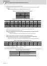
(Table 6) Higher harmonic current generation rate %
Values when basic wave current is 100%.
Check whether the calculated results exceed the limit value.
If the limit value for the higher harmonic current flow is exceeded, consider the higher harmonic measures shown below.
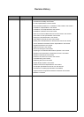
Examples of higher harmonic measures
Incoming power voltage Coefficient a
6.6kV 87.5
22 kV 26.2
33 kV 17.5
66 kV 8.75
77 kV 7.5
Conversion
coefficient
5th- order 7th- order 11th- order 13th- order 17th- order 19th- order 23rd- order 25th- order
6.6kV 3.5 2.5 1.6 1.3 1.0 0.9 0.76 0.70
22kV 1.8 1.3 0.82 0.69 0.53 0.47 0.39 0.36
33kV 1.2 0.86 0.55 0.46 0.35 0.32 0.26 0.24
66kV 0.59 0.42 0.27 0.23 0.17 0.16 0.13 0.12
77kV 0.50 0.36 0.23 0.19 0.15 0.13 0.11 0.10
Conversion
coefficient
5th- order 7th- order 11th- order 13th- order 17th- order 19th- order 23rd- order 25th- order
K32 = 1.8
38.0 14.5 7.4 3.4 3.2 1.9 1.7 1.3
K31 = 3.4
65.0 41.0 8.5 7.7 4.3 3.1 2.6 1.8
Item Details
Power-factor improving capacitor
Higher harmonics are suppressed by adding a leading
capacitor for improving the power factor.
Installation of AC line filter
A reactor and capacitor are combined to reduce the
impedance for specific frequencies.