


2 - 24
2 Wiring and Connection
MITSUBISHI CNC
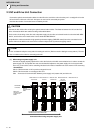
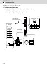
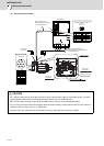
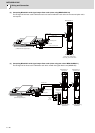
(5) Connecting the HC-H1502
CAUTION
1. For a 3-phase cooling fan, when the phase sequence of the 3-phase power supply is connected reversely, its cooling
capacity degrades due to the reversed rotation direction. Make sure the air blowoff direction.
When the fan rotates reversely, reconnect BU and BW reversely, and then check the blowoff direction.
2. The user must connect the motor thermal(OHS1 OHS2 maximum switching voltage 30V DC) with PLC and construct a
sequence in which an alarm occurs in an OPEN state.
3. Dynamic brake unit is required for HC-H1502. Refer to section "Dynamic brake unit wiring" for details.
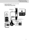
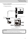
LG
RQ*
SD*
2
4
6
8
10
P5 (+5V)
RQ
SD
BT
1
3
5
7
9
CN2L
CMV1-R10P
8
4
5
7
6
9
10
1
2
3
1 RQ
2 RQ*
3
4 BAT
5 LG(GND)
6 SD
7 SD*
8 P5(+5V)
9
10 SHD
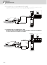
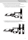
U V W
U
V W
BU BW BV
8
9
2+6
%8
:
%:
%9
2+6
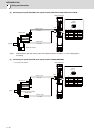
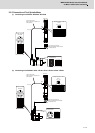
MDS-DH2-V1
(U,V,W) M8screw
(OHS1,OHS2) M4 screw
(BU,BV,BW) M4 screw
Max. 30m
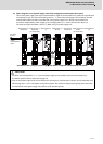
Pin
Name
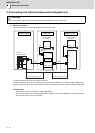
Optional cable: CNV2E
(Refer to Appendix 2 for details
on the cable treatment.)
Power wire and grounding wire
(Refer to Specification manual for details
on selecting the wire.)
Encoder connector
Motor power
terminalblock
Thermal sensor
terminalblock
Encoder connector
Grounding terminal ( ) M6 screw
Cooling fan terminal block
3-phase 400V
power supply
Encoder connector CN2L
NamePin
NamePin
Pin No.
No.9 No.1
No.10 No.2
Exhaust air
Cooling air inlet