


1 - 39
MDS-D2/DH2 Series Instruction Manual
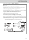
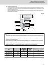
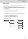
1.5 Installation of the Machine End Encoder
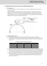
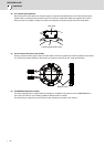
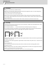
(2) Installing a installation ring
Create a spigot-joint on machine side and fit the installation ring on the inner diameter of the spigot-joint to install
the installation ring. Ensure the accuracy for the dimension of machine side spigot-joint as shown below so as not to
degrade the detection accuracy.
Confirm the gap between the magnetic drum and the sensor head is secured by 0.29mm or more with clearance
gauge etc. after the installation.
[Unit:mm]
[Unit:mm]
CAUTION
1. Do not contact to the magnetic drum when installing the installation ring as it may result in damages of magnetic drum or
sensor head.
2. The sensor head is joined after adjusting the positional relationship with the installation ring beforehand, so do not
remove the sensor head fixing screw.
3. Create a spigot-joint as close to the machine side and fit the installation ring on the spigot-joint to install. Do not center
the core by striking on the installation ring outer diameter. etc.
4. Adherence of foreign materials to the element part of the sensor head (metallic thin film part) could lead to incorrect
detections. Remove with an air blow when foreign materials are adhered so as not to damage them.
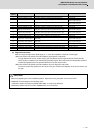
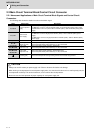
Type
Installation ring
outer diameter
Spigot-joint
inner diameter
(φD)
Spigot-joint
height
(E)
Height from installation ring
bottom surface to magnetic
drum bottom surface
(F)
MBA405W-BE082
MBE405W-BE082
φ140
0
-0.015
φ140
+0.015
0
3.0 to 5.5 9.5±0.2
MBA405W-BF125
MBE405W-BF125
φ190
0
-0.015
φ190
+0.015
0
3.0 to 7.5 11.5±0.2
MBA405W-BG160
MBE405W-BG160
φ242
0
-0.015
φ242
+0.015
0
3.0 to 9.5 13.5±0.2
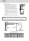
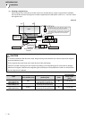
A
A
A
E
F
R1.0
ǾD
0.015
0.02
Installation ring
or less
Spigot-joint
Sensor head
Flange
Shaft