


6 - 43
MDS-D2/DH2 Series Instruction Manual
6.3 Spindle Control Signal
6.3.2 Spindle Control Output (Spindle to NC)
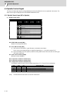
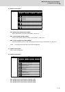
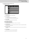
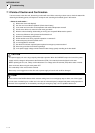
(1) Spindle control output 1
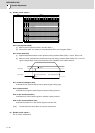
bit0. In ready ON (RDY)
It indicates that the status is in ready ON at RDY=1.
bit1. In servo ON (SRV)
[1] It indicates that the status is in servo ON at SRV=1.
[2] NC position command executes a followed up during SRV=0.
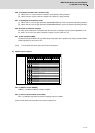
bit7. In alarm (ALMR)
It indicates that drive unit is in some alarm state at ALMR=1.
bit8. In torque limit 1 selection (TL1)
bit9. In torque limit 2 selection (TL2)
bitA. In torque limit 3 selection (TL3)
These are the answer outputs for torque limit 1, 2 and 3 (TL1, TL2 and TL3).
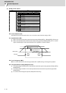
bitC. In in-position (INP)
The status changes to INP=1 when position droop exists within the in-position area set by parameter SP024
(INP) regardless of serve ON or OFF.
bitD. In torque limit (LMT)
It indicates that current command value is limited with motor maximum output current value or torque limit 1, 2
or 3 at LMT=1.
bitF. In warning (WRN)
It indicates that drive unit is in some warning state at WRN=1.
(Note) The bits other than those above are used for maintenance.
Name Details
Spindle control output 1
F E D C B A 9 8 7 6 5 4 3 2 1 0
WRN LMT INP TL3 TL2 TL1
A
LM
R
SRV RDY
bit Details
0
RDY
In ready ON
1
SRV
In servo ON
2
- (For maintenance)
3
- (For maintenance)
4
- (For maintenance)
5
- (For maintenance)
6
- (For maintenance)
7
ALMR
In alarm
8
TL1
In torque limit 1 selection
9
TL2
In torque limit 2 selection
A
TL3
In torque limit 3 selection
B
- (For maintenance)
C
INP
In in-position
D
LMT
In torque limit
E
- (For maintenance)
F
WRN
In warning