


1 - 16
1 Installation
MITSUBISHI CNC
1.2.5 Coupling with the Fittings
[1] If the selection or tension of belt is incorrect, an excessive force is applied to the shaft end and bearings, which may
result in shorter life or damages. We recommend you to adjust the dynamic balance (field balance) before fastening
a belt.
[2] When the load by the belt exceeds the tolerable radial load of the motor, reselect the motor or belt/pulley.
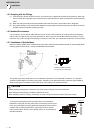
[3] The position deviation in the axial direction between the motor pulley and spindle side pulley should be as small as
possible and perform parallel correcting carefully.
1.2.6 Ambient Environment
If you continue to use the spindle motor with dirt such as oil mist and dust adhered, its cooling performance degrades
and the motor is unable to fully exercise its performance, which may cause the spindle motor overheat alarm. In some
cases this may result in damage to the bearing or cooling fan. Use a filter, etc. to protect the motor from oil mist and dust.
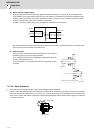
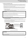
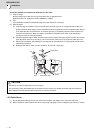
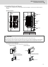
1.2.7 Installation of Spindle Motor
Make sure that the spindle motor is installed so that the motor shaft points from downward to 90° as shown below. When
installing upward more than 90°, contact your Mitsubishi Electric dealer.
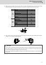
The spindle motor whose motor power line and detection lead wires are connected with connectors, as a standard,
should be installed with the connectors facing down. Installation in the standard direction is effective against dripping.
Measure to prevent oil and water must be taken when not installing in the standard direction.
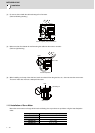
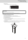
To yield good cooling performance, provide a space of at least 30mm
between the cooling fan and wall. If the motor is covered by a structure and
the air is not exchanged, its cooling performance degrades and the motor is
unable to fully exercise its performance, which may cause the spindle
motor overheat alarm. Do not use the spindle motor in an enclosed space
with little ventilation.
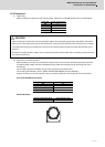
CAUTION
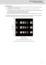
1. Rubber packing for waterproof is attached on the inner surface of the top cover of terminal block.
After checking that the packing is installed, install the top cover.
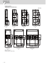
2. When installing a motor on a flange, chamfer(C1) the part of flange that touches inside low part of the motor.
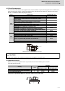
Standard installation direction
for connector connection type
Down
Up
wall
Cooling fan
30mm or more