


7 - 24
7 Troubleshooting
MITSUBISHI CNC
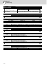
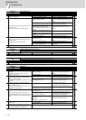
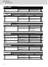
Alarm No.
48
Motor side encoder: Error 5
The motor side encoder (linear scale in the case of linear motor) detected an error.
As details differ for each encoder, refer to section "Encoder alarm".
Investigation details Investigation results Remedies SV SP
1 Check the alarm No. "1B" items.
◯◯
Alarm No.
49
Motor side encoder: Error 6
The motor side encoder (linear scale in the case of linear motor) detected an error.
As details differ for each encoder, refer to section "Encoder alarm".
Investigation details Investigation results Remedies SV SP
1 Check the alarm No. "1B" items.
◯
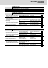
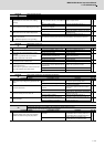
Alarm No.
4A
Motor side encoder: Error 7
The motor side encoder (linear scale in the case of linear motor) detected an error.
As details differ for each encoder, refer to section "Encoder alarm".
Investigation details Investigation results Remedies SV SP
1 Check the alarm No. "1B" items.
◯◯
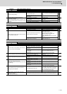
Alarm No.
4B
Motor side encoder: Error 8
The motor side encoder (linear scale in the case of linear motor) detected an error.
As details differ for each encoder, refer to section "Encoder alarm".
Investigation details Investigation results Remedies SV SP
1 Check the alarm No. "1B" items.
◯◯
Alarm No.
4C
Current error at magnetic pole estimate
Current detection failed at the pulse-applied magnetic pole estimation by IPM spindle motor.
Investigation details Investigation results Remedies SV SP
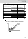
1 Check the pulse-applied time.
The pulse-applied time can be short.
Set the pulse-applied time longer.
Setting parameter:SP142
1) The pulse-applied time (0 to 350)
2) For low-speed coil:1)+1000
3) The polarity of magnetic pole estimate:
Reverse polarity is "-"
After the adjustment, perform the magnetic
pole detection control again.
-
◯
The alarm also occurs after the pulse-applied
time is set.
Replace the unit.
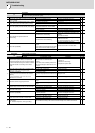
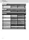
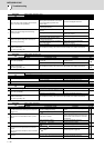
Alarm No.
4D
Dual signal error
An error was detected in the signal related to the dual signal.
Investigation details Investigation results Remedies SV SP
1 When not using dedicated wiring STO function
Is the connector to disable STO installed
correctly?
Install the connector to disable STO
correctly.
◯◯
2 When using dedicated wiring STO function
Is the parameter setting (SV113,SP229/bit8)
correct?
Set SV113,SP229/bit8.
When using dedicated wiring STO function,
set to "1 ".
The error is detected during the servo ON.
Input the STO signal after turning the servo
OFF.
The error is detected during the servo OFF. Remedy the wiring and signal for STO cable.
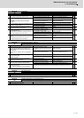
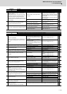
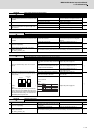
Alarm No.
4E
NC command mode error
The mode outside the specification was input in spindle control mode selection.
Investigation details Investigation results Remedies SV SP
1
Check the wiring and setting environment.
1) Correctly grounded?
2) Any noise generating devices around the unit?
3) Are the speed/position encoder cables correctly
shielded?
1) The grounding is incomplete. Correctly ground.
-
◯
2) The alarm occurs easily when a specific
device operates.
Use noise measures on the device described
on the left.
3) The cable is not correctly shielded. Correctly shield the cable.
No abnormality is found in particular. Replace the drive unit.