


Appendix 1 - 17
MDS-D2/DH2 Series Instruction Manual
Appendix 1.3 Main Circuit Cable Connection Diagram
Appendix 1.3 Main Circuit Cable Connection Diagram
The methods for wiring to the main circuit are shown below.
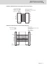
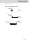
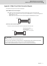
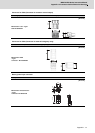
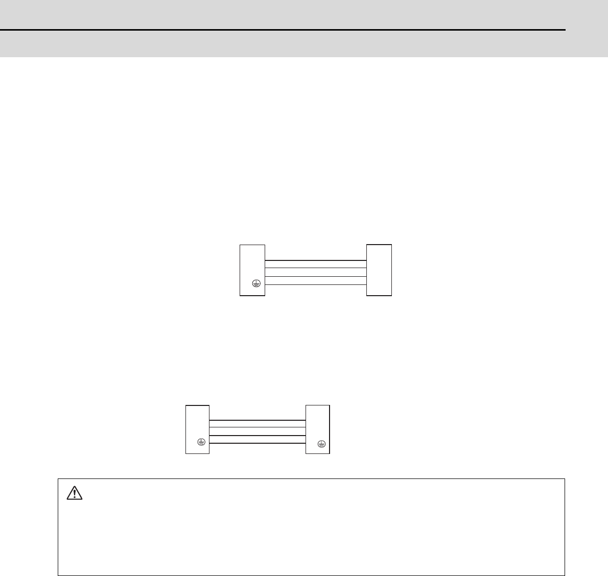
<DRSV1/DRSV2 cable connection diagram>
These cables are used to connect the drive unit's TE1 terminal and HF, HP, HF-H, HP-H series motor.
• DRSV1 cable: This is the power line for the single-axis unit (MDS-D2/DH2-V1-) and dual-axis integrated unit
(MDS-D2/DH2-V2-) L axis.
• DRSV2 cable: This is the power line for the dual-axis integrated unit (MDS-D2/DH2-V2-) M axis.
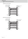
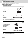
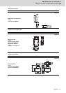
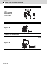
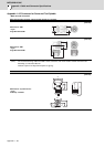
<HF-KP motor cable connection diagram>
This cable is used to connect the drive unit's TE1 terminal and HF-KP series motor.
CAUTION
1. The main circuit cable must be manufactured by the user.
2. Refer to the section "Specification of Peripheral Devices" in Specifications Manual when selecting the wire material.
3. Lay out the terminal block on the drive unit side as shown in "DRIVE SYSTEM DATA BOOK".
4. Refer to "DRIVE SYSTEM DATA BOOK" for details on the motor's connectors and terminal block.
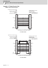
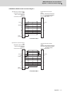
1: U
2: V
3: W
4:
A
B
C
D
Drive unit side Motor side
1: U
2: V
3: W
4:
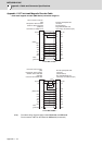
2: U
3: V
4: W
1:
Motor side power connector
(Japan Aviation Electronics Industry)
Plug: JN4FT04SJ1-R
Contact: ST-TMH-S-C1B-100-(A534G)
Drive unit side