


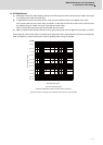

1 - 15
MDS-D2/DH2 Series Instruction Manual
1.2 Installation of Spindle Motor
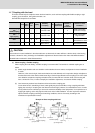
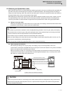
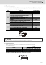
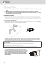
1.2.3 Shaft Characteristics
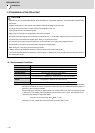
There is a limit to the load that can be applied on the motor shaft. Make sure that the load applied on the radial direction,
when mounted on the machine, is below the tolerable values given below. These loads may affect the motor output
torque, so consider them when designing the machine.
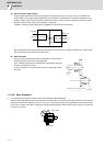
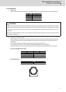
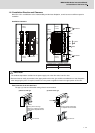
1.2.4 Machine Accuracy
Machine accuracy of the spindle motor's output shaft and around the installation part is as below.
(Excluding special products)
(Note) Refer to Specifications Manual for the frame number of each spindle motor.
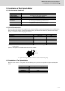
Series Spindle motor Tolerable radial load
200V
series
SJ-VL11-05FZT-S01 98N
SJ-VL2.2-02ZT 196N
SJ-DL5.5/150-01T, SJ-DL5.5/200-01T,SJ-V3.7-02ZT,SJ-VL11-02FZT,
SJ-VL18.5-05FZT
245N
SJ-DL0.75/100-01T, SJ-DL1.5/100-01T 490N
SJ-D3.7/100-01, SJ-D5.5/120-02,SJ-DJ5.5/100-01,SJ-DJ5.5/120-01,
SJ-DL7.5/150-01T,SJ-V2.2-01T,SJ-V7.5-03ZT
980N
SJ-D5.5/100-01, SJ-D5.5/120-01,SJ-DJ7.5/100-01, SJ-DJ7.5/120-01 1470N
SJ-D7.5/100-01,SJ-D7.5/120-01,SJ-D11/100-01,SJ-DJ11/100-01,
SJ-DJ15/80-01,SJ-V11-08ZT,SJ-V11-13ZT,SJ-V11-01T
1960N
SJ-V22-06ZT 2450N
SJ-V15-01ZT,SJ-V15-09ZT,SJ-V18.5-01ZT,SJ-V18.5-04ZT,SJ-V22-01ZT,
SJ-V22-04ZT,SJ-V26-01ZT,SJ-V11-09T,SJ-V15-03T,SJ-V18.5-03T,SJ-V22-05T
2940N
SJ-V37-01ZT, SJ-V45-01ZT, SJ-V22-09T, SJ-VK22-19ZT 3920N
SJ-V55-01ZT 5880N
400V
series
SJ-4-V2.2-03T, SJ-4-V3.7-03T, SJ-4-V3.7-05ZT,SJ-4-V7.5-13ZT 980N
SJ-4-V5.5-07T 1470N
SJ-4-V7.5-12T, SJ-4-V11-18ZT, SJ-4-V11-23ZT 1960N
SJ-4-V26-08ZT 2450N
SJ-4-V15-18T, SJ-4-V18.5-14T, SJ-4-V22-15T, SJ-4-V22-18ZT, SJ-4-V30-15ZT,
SJ-4-V11-21T, SJ-4-V15-20T, SJ-4-V18.5-17T, SJ-4-V22-16T
2940N
SJ-4-V37-04ZT, SJ-4-V45-02T 3920N
SJ-4-V55-03T 5880N
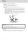
CAUTION
Consider on the machine side so that the thrust loads are not applied to the spindle motor.
Accuracy
Measurement
point
Frame No.
A71, B71, A90, B90,
C90, D90, A112, B112
A160, B160, C160,
A180, B180, A225
Run-out of the flange surface to the output shaft a 0.03mm 0.05mm
Run-out of the flange surface's fitting outer diameter b 0.02mm 0.04mm
Run-out of the output shaft end c 0.01mm 0.02mm
Radial load
(Note) The load point is at the one-half of the shaft length.
a c
b