


7 - 13
MDS-D2/DH2 Series Instruction Manual
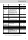
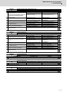
7.3 Troubleshooting
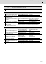
Alarm No.
1A
Sub side encoder: Initial communication error
Initial communication with the machine side encoder failed.
Investigation details Investigation results Remedies SV SP
1
Check the servo parameter (SV025.pen:position
encoder) setting value.
Check the spindle parameter(SP019) setting value.
Are the serial communication type encoder
parameters set for the pulse type encoder?
The value is not set correctly. Correctly set SV025.
◯◯
The value is set correctly. Check the investigation item No. 2.
2
Check the encoder.
Check if the pulse encoder is used for the encoder
specified to be serial.
The pulse encoder is used. Replace the encoder.
◯◯
The serial encoder is used. Check the investigation item No. 3.
3
Jiggle the encoder connectors (drive unit side and
encoder side) and check if they are disconnected.
The connector is disconnected (or loose). Correctly install.
◯
The connector is not disconnected. Check the investigation item No. 4.
4
Turn the power OFF, and check the encoder cable
connection with a tester.
The connection is faulty. Replace the encoder cable.
◯
The connection is normal. Check the investigation item No. 5.
5
Replace with another unit, and check whether the
fault is on the unit side or encoder side.
The alarm is on the drive unit side. Replace the drive unit.
◯
The alarm is on the encoder side. Check the investigation item No. 6.
6
Check if there is any abnormality in the encoder's
ambient environment.
(Ex. Ambient temperature, noise, grounding)
Take remedies according to the causes of the abnormality in the ambient environment.
◯
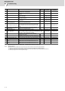
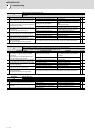
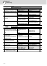
Alarm No.
1B
Sub side encoder: Error 1
The machine side encoder (CN3 side) detected an error. As details differ for each encoder, refer to section "Encoder alarm".
Investigation details Investigation results Remedies SV SP
1
Check whether the servo axis has moved and the
spindle has rotated when an alarm occurred.
The axis has operated. Check the investigation item No. 3.
◯◯
The axis has not operated. Check the investigation item No. 2.
2
Check whether the operation at low speed is
normal.
The operation is normal. Check the investigation item No. 3.
◯◯
The operation is not normal.
Check the cautions at power ON.
[1] Wiring check
[2] Parameter check
3
Jiggle the encoder connectors (drive unit side and
encoder side) and check if they are disconnected.
The connector is disconnected (or loose). Correctly install.
◯◯
The connector is not disconnected. Check the investigation item No. 4.
4
Turn the power OFF, and check the encoder cable
connection with a tester.
The connection is faulty. Replace the encoder cable.
◯◯
The connection is normal. Check the investigation item No. 5.
5
Replace with another unit, and check whether the
fault is on the unit side or encoder side.
The alarm is on the drive unit side. Replace the drive unit.
◯◯
The alarm is on the encoder side. Check the investigation item No. 6.
6
Check if there is any abnormality in the encoder's
ambient environment.
(Ex. Ambient temperature, noise, grounding)
Take remedies according to the causes of the abnormality in the ambient environment.
◯◯
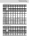
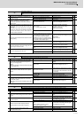
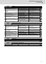
Alarm No.
1C
Sub side encoder: Error 2
The machine side encoder (CN3 side) detected an error. As details differ for each encoder, refer to section "Encoder alarm".
Investigation details Investigation results Remedies SV SP
1 Check the alarm No. "1B" items.
◯
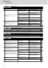
Alarm No.
1D
Sub side encoder: Error 3
The machine side encoder (CN3 side) detected an error. As details differ for each encoder, refer to section "Encoder alarm".
Investigation details Investigation results Remedies SV SP
1 Check the alarm No. "1B" items.
◯
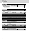
Alarm No.
1E
Sub side encoder: Error 4
The machine side encoder (CN3 side) detected an error. As details differ for each encoder, refer to section "Encoder alarm".
Investigation details Investigation results Remedies SV SP
1 Check the alarm No. "1B" items.
◯