


7 - 14
7 Troubleshooting
MITSUBISHI CNC
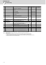
Alarm No.
1F
Sub side encoder: Communication error
An error was detected in communication data with the linear scale or the ball screw side encoder. Or the communication was
interrupted.
Investigation details Investigation results Remedies SV SP
1
Jiggle the encoder connectors (drive unit side and
encoder side) and check if they are disconnected.
The connector is disconnected (or loose). Correctly install.
◯
The connector is not disconnected. Check the investigation item No. 2.
2
Is the encoder cable wired in the same conduit as
the motor's power cable, or are the two cables laid
in parallel near each other?
The cables are wired near each other. (Noise
is entering from the power cable.)
Wire the encoder cable away from the power
cable.
Shield the power cable.
◯
The wires are sufficiently separated. Check the investigation item No. 3.
3
Is the motor FG wire connected only to the drive unit
which drives it?
(Is the motor grounded to one point?)
The motor FG wire is grounded on the motor
side.
Ground the motor to one point, connecting
the wires together on the drive unit side.
◯
The motor is grounded to one point. Check the investigation item No. 4.
4
Turn the power OFF, and check the encoder cable
connection with a tester. (Is the cable shielded?)
The connection is faulty. Replace the encoder cable.
◯
The connection is normal. Check the investigation item No. 5.
5
Replace with another unit, and check whether the
fault is on the unit side or encoder side.
The alarm is on the drive unit side. Replace the drive unit.
◯
The alarm is on the encoder side. Check the investigation item No. 6.
6
Check if there is any abnormality in the encoder's
ambient environment.
(Ex. Ambient temperature, noise, grounding)
Take remedies according to the causes of the abnormality in the ambient environment.
◯
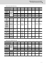
Alarm No.
21
Sub side encoder: No signal2
When an excessive error alarm occurred, no signal from the machine side encoder was detected.
An error was detected in the ABZ-phase in the full closed loop control system.
Investigation details Investigation results Remedies SV SP
1
Check the servo parameter (SV025. pen: machine
side encoder), and spindle parameter (SP019)
setting value.
Are the pulse type encoder parameters set for a
serial communication type encoder?
The value is not set correctly.
Correctly set SV025.pen for the servo and
SP019 for the spindle (including SP097 for
pulse type).
◯◯
The value is set correctly. Check the investigation item No. 3.
2
Jiggle the encoder connectors (drive unit side and
encoder side) and check if they are disconnected.
The connector is disconnected (or loose). Correctly install.
◯◯
The connector is not disconnected. Check the investigation item No. 4.
3
Turn the power OFF, and check the encoder cable
connection with a tester.
The connection is faulty. Replace the encoder cable.
◯◯
The connection is normal. Check the investigation item No. 5.
4
Replace with another unit, and check whether the
fault is on the unit side or encoder side.
The alarm is on the drive unit side. Replace the drive unit.
◯◯
The alarm is on the encoder side. Replace the encoder.
5
Check if there is any abnormality in the encoder's
ambient environment.
(Ex. Ambient temperature, noise, grounding)
Take remedies according to the causes of the abnormality in the ambient environment.
◯◯
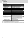
Alarm No.
22
Encoder data error:
Drive unit received a wrong feedback data (scattered data) from the encoder and position deviation occurred.
Investigation details Investigation results Remedies SV SP
1 Check if the installation of the encoder is loosened.
It is loosened. Tightly install the encoder.
◯
It is not loosened. Check the investigation item No. 2.
2
Check if an excessive vibration is occurring during
machining.
An excessive vibration is occurring. Check the installation of the machine.
◯
An excessive vibration is not occurring. Check the investigation item No. 3.
3 Check the investigation item No.2 or subsequent items in Alarm No.21.
◯