


7 - 34
7 Troubleshooting
MITSUBISHI CNC
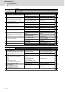
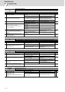
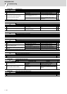
Alarm No.
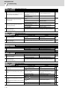
75
Power supply: Overvoltage
L+ and L- bus voltage in main circuit exceeded the allowable value. As the voltage between L+ and L- is high immediately after
this alarm, another alarm may occur if this alarm is reset in a short time. Wait more than 5 min before resetting so that the voltage
drops.
Investigation details Investigation results Remedies CV
1 Check the repeatability.
The alarm occurs each time the motor
decelerates.
Check the investigation item No. 3.
◯
The alarm occurs occasionally. Check the investigation item No. 2.
2 Check the power supply's alarm history.
Auxiliary regeneration frequency over (E8)
occurs just before the over-voltage occurs.
Limit the occurrence of the excessive
instantaneous regeneration by not
decelerating multiple axes at the same time.
◯
Others. Check the investigation item No. 3.
3 Check the power capacity.
The power capacity is insufficient. Increase the power capacity.
◯
The specified power capacity is secured. Check the investigation item No. 4.
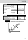
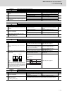
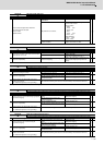
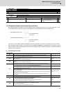
4
Measure the voltage across wires.
[1] Is the voltage 170V or more even when the
motor is accelerating?
The voltage drops to 170V or less
occasionally.
Increase the power capacity.
◯
The difference of the voltage across wires is
10V or more.
Improve the power phase balance.
The difference of the voltage across wires is
less than 10V.
Check the investigation item No. 5.
5
Measure the power voltage with a synchroscope,
and check whether there is any distortion.
[1] Are there any other devices causing the power
distortion?
The power voltage is distorted.
Improve the source of the distortion.
Install an AC reactor.
◯
The power voltage waveform is not
abnormal.
Check the investigation item No. 6.
6
Check if there is any abnormality in the unit's
ambient environment.
(Ex. Noise, grounding, etc.)
Take remedies according to the causes of the abnormality in the ambient environment.
◯
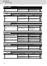
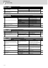
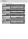
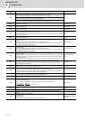
Alarm No.
76
Power supply: Function setting error
The rotary switch setting of external emergency stop is not correct, or a wrong external emergency stop signal is input.
Investigation details Investigation results Remedies CV
1 Check the rotary switch setting.
When using external emergency stop, rotary
switch is not set to "4".
Set the rotary switch to "4".
◯
2
Check if there is any abnormality in the unit's
ambient environment.
No abnormality is found in particular. Replace the drive unit.
◯
The grounding is incomplete.
Take remedies according to the causes of
the abnormality.
Additionally ground and review.
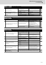
Alarm No.
77
Power supply: Power module overheat
Thermal protection function in the power module has started its operation.
Investigation details Investigation results Remedies CV
1 Confirm that the fan is properly rotating.
Large amounts of cutting oil or cutting chips,
etc., are adhered, or the rotation is slow.
Clean or replace the fan.
◯
The fan is properly rotating. Check the investigation item No. 2.
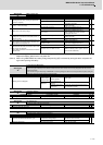
2 Check whether the heat dissipating fins are dirty.
Cutting oil or cutting chips, etc., are adhered,
and the fins are clogged.
Clean the fins.
◯
The fins are normal. Check the investigation item No. 3.
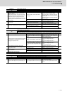
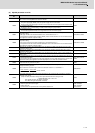
3
Measure the power supply unit's ambient
temperature.
55°C or more
Improve the ventilation and cooling for the
power distribution panel.
◯
Less than 55°C. Check the investigation item No. 4.
4
Check if there is any abnormality in the unit's
ambient environment.
(Ex. Ambient temperature, noise, grounding)
Take remedies according to the causes of the abnormality in the ambient environment.
◯
Alarm No.
80
Main side encoder cable error
A pulse type cable is used for the motor side encoder.
Investigation details Investigation results Remedies SV SP
1
Check the parameters.
Servo:SV025 = "x200"
Spindle:SP031 = "x200"
And then, check the connected cable and the
encoder.
The cable type is pulse. Replace the cable to the serial type.
◯◯
There is no problem with the selection of the
encoder and cable.
Replace the encoder or cable.