


2 - 32
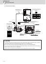
2 Wiring and Connection
MITSUBISHI CNC
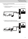
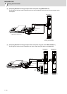
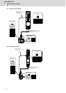
(3) Connecting the HF-SP406
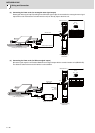
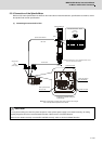
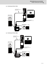
(4) Connecting the HF204
A
B
C
D
CE05-2A18-10PD
U
V
W
A
B
C
D
CMV1-R10P
8
4
5
7
6
9
10
1
2
3
1 RQ
2 RQ*
3 CNT
4 BAT
5 LG(GND)
6 SD
7 SD*
8
9
10 SHD
P5 (+5V)
U V W
CN2L
MDS-D2-SP
LG
RQ*
SD*
2
4
6
8
10
P5(+5V)
RQ
SD
BT
1
3
5
7
9
Power connector
Ground
Optional cable: CNV2E
(Refer to Appendix 2 for details on the
cable treatment.)
Max : 30m
Encoder connector
NamePin
NamePin
Power wire and grounding wire
(Refer to Specification manual for details
on selecting the wire.)
NamePinNamePin
Pin No.
Encoder connector : CN2L
No.9 No.1
No.10 No.2
A
B
C
D
CE05-2A22-22PD
U
V
W
A
B
C
D
CMV1-R10P
8
4
5
7
6
9
10
1
2
3
1 RQ
2 RQ*
3 CNT
4 BAT
5 LG(GND)
6 SD
7 SD*
8
9
10 SHD
P5 (+5V)
MDS-D2-SP
U V W
LG
RQ*
SD*
2
4
6
8
10
P5(+5V)
RQ
SD
BT
1
3
5
7
9
Power connector
Ground
Optional cable: CNV2E
(Refer to Appendix 2 for details on the
cable treatment.)
Max : 30m
Encoder connector
NamePin
NamePin
NamePinNamePin
Pin No
Encoder connector : CN2
Power wire and grounding wire
(Refer to Specification manual for details
on selecting the wire.)
No.9 No.1
No.10 No.2