


1 - 13
MDS-D2/DH2 Series Instruction Manual
1.2 Installation of Spindle Motor
1.2.2 Balancing the Spindle Motor (Unit)
When a spindle motor is driven at a high speed with unbalance generated on the rotor, the whirling load is generated and
the load to the motor's internal bearings is increased. Thus abnormal vibration, and/or damages known as fretting or
flaking occurs to the bearings, which may result in shorter bearing life. Therefore, it is important to balance the rotation so
that great vibration does not occur during rotation at high speed.
When balancing the spindle motor, perform to the entire rotational objects including the gear, pulley, coupling, etc. that
are attached directly on the motor shaft. Provide a balancing mechanism including screw holes on the fittings while
measuring the vibration so that the vibration is suppressed to the specified level or lower during high speed rotation.
(1) Fittings for the motor shaft
When you select fittings for the motor shaft, such as a gear, pulley, and coupling, choose those that meet the motor
specifications (shaft diameter, rotation speed and output torque).
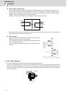
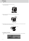
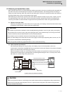
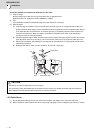
(2) How to measure the unbalance
After attaching the fittings such as gear, pulley, and coupling, carry out no-load operation, and use an
accelerometer or vibrometer compatible with frequency analysis to confirm the vibration on the points as illustrated
below (on the brackets where the bearings are stored).
Make sure to place the motor on a cushioning mat to avoid vibration to the spindle from external sources during
measurement. Reaction torque is generated when accelerating/decelerating the motor, so securely fix the motor
with a belt, etc. to avoid rolling during measurement.
CAUTION
1. We consider key-less shaft as standard in order to simplify balancing procedure of such as gear, pulley, and coupling.
We recommend you to choose a gear, pulley and coupling that have a fully symmetric shape, and arrange screw holes
on their end faces at short and equal intervals in the circumferential direction.
2. Use a fastener such as a shaft lock element to fix those fittings to the motor shaft.
3. When you attach fittings to the motor shaft, be careful not to apply excessive impact by striking with a hammer, etc. This
may cause the shaft distortion and bearing damage.
4. When using screws for balancing, apply thread locker on the screws after balancing.
CAUTION
1. Make sure to place the motor on a cushioning mat to avoid resonance with surrounding devices during measurement.
2. Always secure the spindle motor body with a belt, etc. to prevent it from rolling due to the reaction torque generated
during acceleration/deceleration.
Load side bracket (axial direction)
Counter load side bracket (horizontal)
side bracket (horizontal, vertical)
Locations where motor vibration is measured
Measuring device
Coupling
Cushioning mat