


2 - 49
MDS-D2/DH2 Series Instruction Manual
2.8 Peripheral Control Wiring
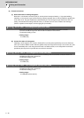
2.8.4 Proximity Switch Orientation
(1) Electrical specifications
Use a proximity switch which satisfies the following specifications.
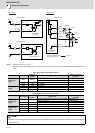
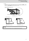
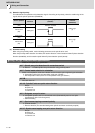
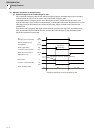
(2) Connecting with the drive unit
Item Specification
Output method DC double wire system /three wire system
Power supply voltage 24V DC
Response frequency 400Hz or more
Load current 14mA or more
Residual voltage 4V or less
Leakage current 1mA or less
CAUTION
1. Supply the 24VDC power externally.
2. Install a proximity switch at the spot that rotates in the ratio of 1:1 to the spindle.
3. Set the spindle parameter to the pulley ratio for belt drive or to the gear ratio for gear drive.
20
DICOM
13
DI1
MDS-D2/DH2-SP
4.1k
CN9
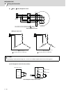
DICOM
MDS-D2/DH2-SP
4.1k
CN9
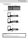
DICOM
MDS-D2/DH2-SP
4.1k
CN9
24G
20
13
DI1
20
13
DI1
24VDC
Current direction
Proximity switch
Shield
Case
ground
Detection circuit
24VDC
Current direction
Proximity switch
Shield
Case
ground
Detection circuit
Select the polarity of DICOM
< Connection details: For proximity switch of two wire system >
< Connection details: For proximity switch of three wire system >
24VDC
Current direction
Proximity switch
Shield
Case
ground
Detection circuit
< Connection details: For proximity switch of two wire system >
< Connection details: For proximity switch of three wire system >
(a) When DICOM is connected to 24V
(b) When DICOM is connected to 24G
Not usable.