


7 - 10
7 Troubleshooting
MITSUBISHI CNC
7.3 Troubleshooting
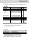
Follow this section to troubleshoot the alarms that occur during start up or while the machine is operating. If the state is
not improved with the following investigations, the drive unit may be faulty. Exchange the unit with another unit of the
same capacity, and check whether the state is improved.
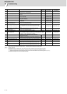
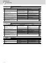
7.3.1 Troubleshooting at Power ON
If the NC system does not start up correctly and a system error occurs when the NC power is turned ON, the drive unit
may not have been started up properly. Check the LED display on the drive unit, and take measures according to this
section.
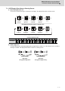
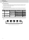
The drive unit has started up normally if the following type of emergency stop (E7) is displayed on the display unit's LED
display.
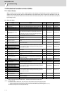
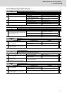
LED
display
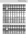
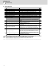
Symptom Cause of occurrence Investigation method Remedy
AA
Initial communication with the
CNC was not completed
correctly.
The drive unit axis No. setting is
incorrect.
Is there any other drive unit that has the same
axis No. set?
Set correctly.
The CNC setting is incorrect. Is the No. of CNC controlled axes correct? Set correctly.
Communication with CNC is
incorrect.
Is the connector (CN1A, CN1B) connected? Connect correctly.
Is the cable broken? Replace the cable.
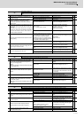
Ab
Initial communication with the
CNC was not carried out.
The axis is not used, the setting is
for use inhibiting.
Is the DIP switch set correctly? Set correctly.
Communication with CNC is
incorrect.
Is the connector (CN1A, CN1B) connected? Connect correctly.
Is the cable broken? Replace the cable.
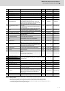
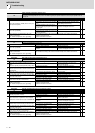
12
An error was detected in the
unit's memory and IC during the
self-diagnosis at power ON.
The CPU peripheral circuit is
abnormal.
Check the repeatability. Replace the unit.
Check whether there is any abnormality with
the unit's surrounding environment, etc.
Improve the
surrounding
environment.
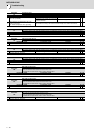
F1
F+axis No.
E7
Emergency stop
Not lit F2
F+axis No.
E7
Emergency stop
Normal drive unit LED display at NC power ON (for 1st axis)