


5 - 37
MDS-D2/DH2 Series Instruction Manual
5.3 Characteristics Improvement
(2) Setting and adjusting LMC compensation type 3
LCM compensation type 3 can be used to accommodate quadrant projection changes that accompany feed rate
and circular radius changes which could not be accommodated by LCM compensation type 2. In this case, on a
machine model where the travel direction is reversed, the effect caused by torsion or expansion and contraction on
the machine system are also considered in addition to the friction, with compensation occurring in accordance with
the changes in the cutting conditions.
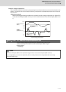
Adjust Compensation parameter (SV016, SV041), a basis of compensation, while measuring roundness at low
speed. Then adjust viscous coefficient (SV086) while measuring roundness at high speed.
LMC compensation type 3 parameter adjustments should be made while measuring an electrical end position FB
waveform by the NC sampling function.
<Adjustment method>
[1] Turn the NC side machine error compensation (pitch error compensation, relative position compensation or
backlash compensation) OFF.
[2] Set servo function selection 5 SV082/ bit=1. (The LMC compensation type 3 will start).
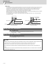
[3] Set a value double the friction torque to the lost motion compensation 1 (SV016). The SV016 setting value will
be used for compensation in the positive and negative directions when the lost motion compensation 2
(SV041) is 0.
[4] Set the initial value, SV016 x 200 to the lost motion compensation viscous coefficient (SV086).
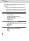
[5] Perform a roundness measurement at such speed as radius R=100mm and feedrate F=1000mm/min and
adjust SV016 value.
[6] Set SV041, when changing the compensation amount in the direction for compensation. The setting of the
compensation direction is shown below with the setting of CW/CCW in the NC parameter. If compensating
only one direction, set –1 to the side not to be compensated.
[7] Perform a roundness measurement at such speed as radius, R=100mm and feedrate, F=5000mm/min. (Select
a condition to be used for the actual cutting according to the machine's specification.) Adjust viscous
coefficient (SV086) by increasing and reducing it approx. ±500 gradually to have minimum quadrant
protrusion.
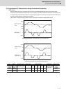
[8] After adjusting SV086, verify its accuracy by performing roundness measurement at low speed again.
[9] At this time, if requiring to improve the accuracy further, adjust the spring constant (SV085) in increments of
about 50 while performing the machine roundness measurement at low speed.
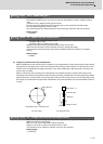
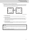
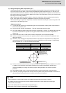
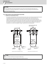
Compensation point CW CCW
A X axis: SV041 X axis: SV016
B Y axis: SV016 Y axis: SV041
C X axis: SV016 X axis: SV041
D Y axis: SV041 Y axis: SV016
POINT
1. As the acceleration of circular feed increases, the quadrant protrusion tends to get larger. Therefore,
the quadrant protrusion gets larger as the circular feedrate increases for the same radius and as radius gets
smaller for the same feedrate.
2. Torque offset (SV032) does not work for LMC compensation type 3.
3. Always set 0 to the lost motion compensation timing (SV039:LMCD).
+Y
-Y
+X-X
A
T
he X axis command direction
c
hanges from + to -.
D
The Y axis command direction
changes from + to
-
.
B
The Y axis command direction
changes from - to +.
C
T
he X axis command direction
changes from - to +.