


4 - 75
MDS-D2/DH2 Series Instruction Manual
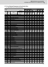
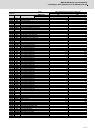
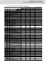
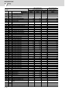
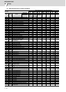
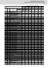
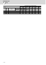
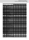
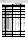
4.3 Setting the Initial Parameters for the Spindle Drive Unit
(4) 200V Standard motor SJ-DL Series (Low-inertia) / (Hollow shaft)
Motor
Parameter
200V Standard motor
SJ-DL Series (Low-inertia)
200V Standard motor
SJ-DL Series (Hollow shaft)
SJ-DL5.5/150-01T SJ-DL5.5/200-01T SJ-DL7.5/150-01T SJ-DL5.5/200-01T-S
No. Abbrev. Details
MDS-D2-SP- 160 160 160 160
MDS-D2-SP2- 16080(L) 16080(L) 16080(L) 16080(L)
SP001 PGV Position loop gain non-interpolation mode 15 15 15 15
SP002 PGN Position loop gain interpolation mode 33 33 33 33
SP003 PGS Position loop gain spindle synchronization 15 15 15 15
SP004 000 0
SP005 VGN1 Speed loop gain 1 150 150 150 150
SP006 VIA1 Speed loop lead compensation 1 1900 1900 1900 1900
SP007 VIL1 Speed loop delay compensation 1 000 0
SP008 VGN2 Speed loop gain 2 150 150 150 150
SP009 VIA2 Speed loop lead compensation 2 1900 1900 1900 1900
SP010 VIL2 Speed loop delay compensation 2 000 0
SP011 000 0
SP012 000 0
SP013 000 0
SP014 PY1 Minimum excitation rate 1 50 50 50 50
SP015 PY2 Minimum excitation rate 2 100 100 100 100
SP016 DDT Phase alignment deceleration rate 20 20 20 20
SP017 SPEC1 Spindle specification 1 000C 000C 000C 000C
SP018 SPEC2 Spindle specification 2 0000 0000 0000 0000
SP019 RNG1 Sub side encoder resolution 2000 2000 2000 2000
SP020 RNG2 Main side encoder resolution 2000 2000 2000 2000
SP021 OLT Overload detection time constant 60 60 60 60
SP022 OLL Overload detection level 120 120 120 120
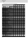
SP023 OD1
Excessive error detection width
(interpolation mode - spindle
synchronization)
120 120 120 120
SP024 INP In-position width 875 875 875 875
SP025 INP2 2nd in-position width 875 875 875 875
SP026 TSP Maximum motor speed 15000 20000 15000 20000
SP027 ZSP Motor zero speed 50 50 25 50
SP028 SDTS Speed detection set value 1500 2000 1500 2000
SP029 SDTR Speed detection reset width 30 30 30 30
SP030 SDT2 2nd speed detection setting value 000 0
SP031 MTYP Motor type 2200 2200 2200 2200
SP032 PTYP
Power supply type/ Regenerative resistor
type
0000 0000 0000 0000
SP033 SFNC1 Spindle function 1 0000 0000 0000 0000
SP034 SFNC2 Spindle function 2 0000 0000 0000 0000
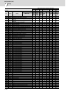
SP035 SFNC3 Spindle function 3 1600 1600 1600 1600
SP036 SFNC4 Spindle function 4 0000 0000 0000 0000
SP037 JL Load inertia scale 100 100 100 100
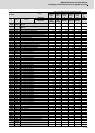
SP038 FHz1 Notch filter frequency 1 000 0
: ::: :
SP046 FHz2 Notch filter frequency 2 000 0
SP047 EC Inductive voltage compensation gain 100 100 100 100
SP048 LMC1 Lost motion compensation 1 000 0
: ::: :
SP052 DFBN Dual feedback control non-sensitive band 000 0
SP053 ODS
Excessive error detection width (non-
interpolation mode)
3000 4000 3000 4000
SP054 ORE
Overrun detection width in closed loop
control
000 0
SP055 EMGx Max. gate off delay time after emergency stop 20000 20000 20000 20000
SP056 EMGt
Deceleration time constant at emergency
stop
300 300 300 300
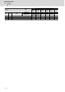
SP057 GRA1 Spindle side gear ratio 1 111 1
SP058 GRA2 Spindle side gear ratio 2 111 1
SP059 GRA3 Spindle side gear ratio 3 111 1
SP060 GRA4 Spindle side gear ratio 4 111 1
SP061 GRB1 Motor side gear ratio 1 111 1
SP062 GRB2 Motor side gear ratio 2 111 1
SP063 GRB3 Motor side gear ratio 3 111 1
SP064 GRB4 Motor side gear ratio 4 111 1
SP065 TLM1 Torque limit 1 10 10 10 10
SP066 TLM2 Torque limit 2 10 10 10 10
SP067 TLM3 Torque limit 3 10 10 10 10
SP068 TLM4 Torque limit 4 10 10 10 10
SP069 PCMP Phase alignment completion width 875 875 875 875
SP070 KDDT Phase alignment deceleration rate scale 000 0
SP071 DIQM
Variable current limit during deceleration,
lower limit value
75 55 40 55
SP072 DIQN
Variable current limit during deceleration,
break point speed
11400 11400 6600 11400
SP073 VGVN Variable speed gain target value 000 0