


6 - 6
6 Spindle Adjustment
MITSUBISHI CNC
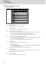
【#13005】 SP005 VGN1 Speed loop gain 1
Set the speed loop gain.
Set this according to the load inertia size.
The higher setting value will increase the accuracy of control, however, vibration tends to occur.
If vibration occurs, adjust by lowering by 20 to 30%.
The final value should be 70 to 80% of the value at which the vibration stops.
---Setting range---
1 to 9999
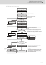
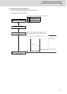
(4) Adjusting the position loop gain (SP001: PGV non-interpolation mode position loop gain)
After setting the speed gain, in order to perform acceleration/deceleration operation, set the position loop gain
(SP001) by increasing its setting value from 15. When overshooting occurs at the time of acceleration/deceleration
completion, or when oscillation of the q axis current command gets bigger during a set rotation, the position loop
gain is in limit state. Note that standard position loop gain below is set for the setting gain.
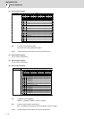
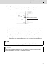
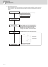
Method for checking the limitation of position loop gain
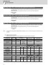
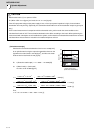
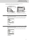
(Example)As the closest value should be selected from the standard setting range shown below, set 47 to SP001
when the limit gain is 55.
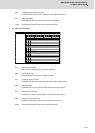
【#13001】 SP001 PGV Position loop gain non-interpolation mode
Set the position loop gain for "Non-interpolation" control mode.
When the setting value increases, the command tracking ability will enhance and the positioning
settling time can be shorter. However, the impact on the machine during acceleration/deceleration
will increase.
Use the selection command, the control mode "bit 2, 1, 0 = 000" in control input 4.
(Note) The control mode is commanded by NC.
---Setting range---
1 to 200 (1/s)
CAUTION
Change "Excessive error detection width" (SP053) when "Position loop gain" (SP001) is changed.
Standard position loop gain 15 18 21 23 26 33 38 47 60 70
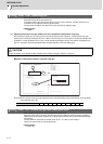
The gain when
overshooting occurs is the
limit.
When oscillation gets bigger
is the limit.
Speed waveform (Ch1: Speed feedback)
Current feedback waveform (Ch2: Current feedback)