


2 - 42
2 Wiring and Connection
MITSUBISHI CNC
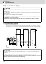
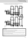
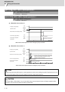
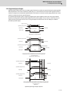
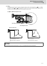
(Note) Do not connect "(1)" or "(2)".
If a ground of the external 24V power is same as the 24V power in the drive unit, a fault or abnormal operation could
occur.
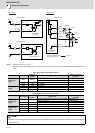
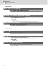
Servo input/output signal (CN9 connector)
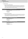
Spindle input/output signal (CN9 connector)
Device name
Connector
pin No.
Signal name
Signal changeover
parameter
Servo input
signal
MPI1 CN9-13
SLS(Safely Limited Speed) function door state signal SV082/bitF-C=1
Battery box voltage drop signal SV082/bitF-C=2
MPI2 CN9-2 (Reservation)
MPI3 CN9-3 (Reservation)
Servo output
signal
MPO1 CN9-8 (Reservation)
MPO2 CN9-18 Servo specified speed signal SV082/bit9,8=01
MPO3 CN9-16 (Reservation)
Device name
Connector
pin No.
Signal name
Signal changeover
parameter
Spindle input
signal
MPI1 CN9-13
SLS(Safely Limited Speed) function door state signal SP227/bitF-C=1
Proximity switch signal SP227/bitF-C=4
MPI2 CN9-2 (Reservation)
MPI3 CN9-3 (Reservation)
Spindle input
signal
MPO1 CN9-8 Coil changeover signal
MPO2 CN9-18 Spindle specified speed signal SP229/bitC=1
MPO3 CN9-16 (Reservation)
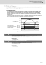
POINT
The different signal changeover parameter setting is not available for the same connector pin number of each axis in 2-axis
or 3-axis drive unit.
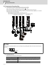
DICOM
DI1
13
20
1A
4A
4.1k
24V
24V
24V
(1)
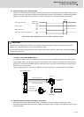
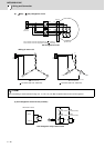
8
18
16
10
MPO1
MPO2
MPO3
24G
D01
D02
D03
4.1k
(2)
CN9 connector CN9 connector
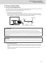
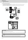
Servo/spindle
drive unit
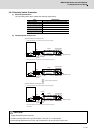
CN24 connector
Switch
Power supply unit
Input circuit
Output circuit
Servo/spindle
drive unit
Relay, etc.
The part indicated by the " " must be
prepared by the user.
Switch