


4 - 37
MDS-D2/DH2 Series Instruction Manual
4.2 Setting the Initial Parameters for the Servo Drive Unit
bit 3 :
Not used. Set to "0".
bit 2 :
Not used. Set to "0".
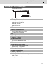
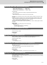
bit 1-0 : vcnt Speed loop delay compensation changeover type selection
Normally, use "Changeover type 2".
bit1,0=
00: Disable
01: Changeover type 1
10: Changeover type 2
11: Setting prohibited
Related parameters: SV007
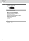
【#2228(PR)】 SV028 MSFT Magnetic pole shift amount (for linear/direct-drive motor)
Set this parameter to adjust the motor magnetic pole position and encoder's installation phase when
using linear motors or direct-drive motors.
During the DC excitation of the initial setup (SV034/bit4=1), set the same value displayed in "AFLT
gain" on the NC monitor screen.
Related parameters: SV034/bit4, SV061, SV062, SV063
For general motor:
Not used. Set to "0".
---Setting range---
-18000 to 18000 (Mechanical angle 0.01°)
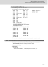
【#2229】 SV029 VCS Speed at the change of speed loop gain
Noise at high speed rotation including rapid traverse can be reduced by lowering the speed loop gain
at high speeds.
Set the speed at which the speed loop gain changes. Use this with SV006 (VGN2).
When not using, set to "0".
---Setting range---
0 to 9999 (r/min)
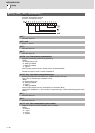
【#2230】 SV030 IVC Voltage non-sensitive band compensation
When 100% is set, the voltage reduction amount equivalent to the logical non-energization in the
PWM control will be compensated.
When "0" is set, 100% compensation will be performed.
Adjust in increments of 10% from the default value of 100%.
If increased too much, vibration or vibration noise may be generated.
---Setting range---
0 to 255 (%)