


7 - 41
MDS-D2/DH2 Series Instruction Manual
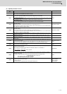
7.3 Troubleshooting
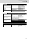
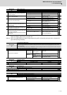
(2) Spindle parameter error No.
Error parameter
No.
Details Related parameters
13017
The motor selected is of a motor series different from the drive unit's input voltage (200V/400V).
Or a motor of an incompatible motor series is selected.
SP017
13032
For the MDS-D2/DH2 Series:
The power supply type (SP032) is set, but a power supply unit is not connected.
Always set the power supply type for the drive unit connected last on the NC optical communication cable.
SP032For the MDS-DM2 Series:
Set SP032 to 0019(normal setting), or 0059 (external emergency stop function).
For the MDS-DJ Series:
The selected regenerative resistor is not supported in the drive unit of this capacity.
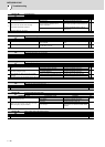
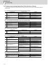
13097
-The expansion sub side encoder resolution (SP097) is set to "0" for a encoder that requires the resolution
expansion setting.
If the upper 16 bits for the encoder resolution are "0", this should be set to "-1".
-The expansion sub side encoder resolution (SP097) is set to a value other than "0" for a encoder that does
not support the resolution expansion setting.
SP019,SP031,SP097
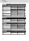
13098
-The expansion main side encoder resolution (SP098) is set to "0" for a encoder that requires the resolution
expansion setting.
If the upper 16 bits for the encoder resolution are 0, this should be set to "-1".
-The expansion main side encoder resolution (SP098) is set to a value other than "0" for a encoder that does
not support the resolution expansion setting.
SP020,SP031,SP098
13125
When the DC excitation mode (SP225/bit4) is set, the initial DC excitation level (SP125) is set to a value
outside the setting range.
SP225, SP125
13126
When the DC excitation mode (SP225/bit4) is set, the final DC excitation level (SP126) is set to a value
outside the setting range.
SP225, SP126
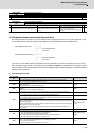
13127
When the DC excitation mode (SP225/bit4) is set, the initial DC time (SP127) is set to a value outside the
setting range.
SP225, SP127
13142
-The pulse application time for an IPM spindle motor is excessive. Set the pulse application time (SP142) to
a value lower than 350μs.
-The coil switch function is disabled and the pulse application coil for an IPM spindle motor is set to the low-
speed coil. Set the pulse application coil to the high-speed coil, or enable the coil switch function.
SP017,SP018,SP142,
SP226
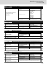
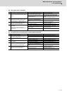
13225
The DC excitation mode (SP225/bit4) has been set before the axis passes the Z phase. Set the DC excitation
mode after the axis passes the Z phase.
SP225
13238
The safety observation safety speed (SP238) and the safety observation safety motor speed (SP239) do not
satisfy the following equation:
(Round down the first decimal place. When the calculation results in "0", set SP239 to 1.)
SP238,SP239
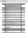
13239
The safety observation safety motor speed calculated from the actual gear ratio exceeds the overspeed
detection motor speed.
(Note) The safety observation safety motor speed calculated from the actual gear ratio
= SP238:SSCFEED / 360 × PC2 / PC1
PC2: Spindle side gear ratio (SP057 to SP060)
PC1: Motor side gear ratio (SP061 to SP064)
SP239
13255
The following settings are overflowing:
-Electronic gear and motor side gear
-Position loop gain
-Conversion from the speed detection unit to position detection unit
SP057 to SP060
SP061 to SP064
SP001 to SP003
SP019, SP020
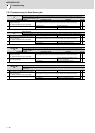
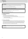
SP057 : GRA1
SP061 : GRB1
SP239 : SSCRPM
360
×
=
SP238 : SSCFEED