


3 - 16
3 Safety Function
MITSUBISHI CNC
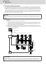
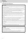
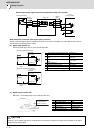
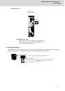
External input/output signal connection example when using a NC controller
Detail description of external input/output signal connection
Details of the input/output signal as stated before (refer to "I/O class" in the table) are shown below. Connect to an
external device by referring to this section.
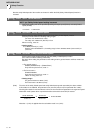
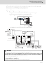
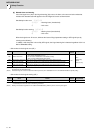
(a) Digital input interface: DI
Provide a signal with a relay or open-collector transistor.
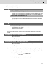
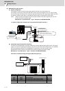
(b) Digital output interface: DO
Maximum 1.3V of voltage drop occurs inside the drive unit.
1 Input voltage at external contact ON 24VDC±10%
2 Input current at external contact ON 10mA or more
3
Input voltage at external contact
OFF
4V or less
4
Input current at external contact
OFF
2mA or less
5 Input resistance 4kΩ
6 Tolerable chattering time 1ms or less
7 Input signal holding time 600ms or more
8 Input circuit operation delay time 10ms typ 30ms or less
1 Insulation method Insulation
2 Rated load voltage 24V
3 Rated current 40mA or less
4 Maximum current 50mA or less
5 Rush current 100mA or less
6 Internal voltage drop 1.3V or less
CAUTION
Maximum 1.3V of voltage drop occurs inside the drive unit. Select an external connection device operable in the output
voltage after the voltage drop.
STO1 4
STO_COM
3
STO2
5
TOF_COM
TOF1
8
6
TOF27
Door signal contact
Drive unit
Shutoff
command
Shutoff
effect
IO unit
for NC controller
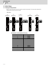
STO_COM
STO1/STO2
4kΩ
䊄䊤䉟䊑䊡䊆䉾䊃
±10%
200mA
䊄䊤䉟䊑䊡䊆䉾䊃
±10%
200mA
STO_COM
STO1/STO2
4kΩ
24VDC
Drive unit
Switch
24VDC
[1] Sink input/output interface
[2] Source input/output interface
Switch
Drive unit
TOF1/TOF2
OF_COM
Drive unit
The drive unit is
damaged when the
polarity is reversed.
(Note) 24VDC±10%
Load