


5 Servo Adjustment
MITSUBISHI CNC
5 - 2
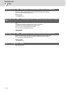
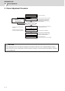
5.1 Servo Adjustment Procedure
CAUTION
Perform adjusting the servo in the factory configuration of the machine. When the servo is adjusted without having an
enough running-in or a cover, friction torque, machine resonance frequency or resonance gain may be different, resulting in
an incorrect adjustment.
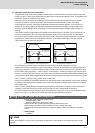
NO
YES
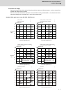
Mainly measure the position droop
waveform.
Measure the electrical end position
FB (encoder position FB) waveform.
Setup has completed.
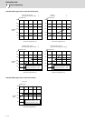
Set speed loop gain
Set position loop gain
Measures against the vibration
Notch filter
Jitter compensation
Variable speed loop gain
Vibration occurs?
Adjusting servo
Set the functions of overload detection,
deceleration control at emergency stop,
vertical axis dro
p
u
p
r evention
,
etc .
Improve protrusion at quadrant
Perform lost motion compensation
Set protective function
Adjusting servo completed
Accuracy adjustment of
the electrical end position FB has completed.
Perform the adjustment so that vibration or
overshooting does not occur.
Look for the maximum value not causes
machine resonance. The final setting
value should be 70 to 80% of the
maximum value at which the machine
does not resonate.