


6 - 5
MDS-D2/DH2 Series Instruction Manual
6.1 Adjustment Procedures for Each Control
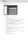
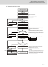
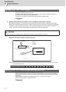
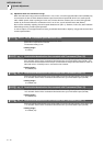
(3) Adjusting the speed loop parameter
CH1
CH2
Yes
NO
YES
NO
0
0
NO
YES
Stops at servo ON status
Increase the value up to where
resonance occurs.
Set SP005 (standard setting 150)
Command M19 (orientation stop)
Adjust speed loop gain
Set SP001=15
Resonance occurs?
Increase SP005 by +20
Command M19 (orientation stop)
Increase SP005 by -20
Subtract 20 from SP005
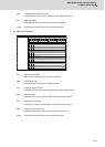
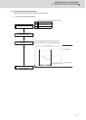
Acceleration/deceleration
operation
Resonance
(abnormal noise) or abnormal
operation occurs?
Command M19 (orientation stop)
Waveform
for Ref.
0.045
°
or less
Position droo
p
Adjustment completed
Multiply SP005 by 0.9
Subtract 3 from SP005
Is droop oscillation
0.045°p-p or less?
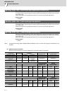
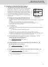
Note that the maximum setting value is as follows:
SP005(max) ≤ 150 × inertia ratio
(Inertia ratio total inertia/motor inertia
(Example)
When inertia rate is double and the determined gain is
350, the setting value for SP005 is 315, which is 90%
of the determined gain, however,the setting value for
SP005 should be 300, because the maximum setting
value is 150×2(inertia rate)=300.
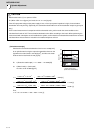
Executes acceleration/deceleration operation in phase
up to maximum rotation speed from 0.
(Note)
When the maximum speed is 10000r/min, executes in
approx. 1000r/min increments, divided by 10.
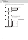
(Note)
NC analyzer cannot create a program when acquiring a
spindle waveform. The program is created on the NC
side.
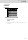
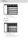
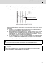
< NC Analyzer setting (Time-series data measurement) >
Set the "Time-series data
measurement" with NC Analyzer
as shown on the right.
Get
Waveform type
Position droop
Current feedback
Current feedback