


7 - 8
7 Troubleshooting
MITSUBISHI CNC
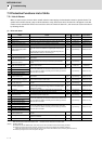
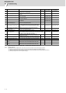
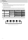
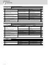
(2) Power supply alarm
(Note 1) If a power supply alarm (60 to 77) occurs, all servos will stop with the dynamic brakes, and all spindles will coast to a stop.
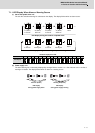
(Note 2) "b", "C" and "d" displayed on the power supply unit's LED as a solid light (not flickering) do not indicate an alarm.
(Note 3) Check the LED display of the power backup unit to identify what alarm is occurring to the power backup unit.
**Refer to "9.5.2 List of Power Backup Function Alarms".
(Note 4) When the power supply alarm (6F) is detected in the 2nd part system, the reset method differs depending on the detected power supply alarm.
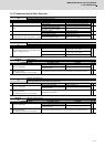
No. Name Details
Reset
method
61 Power supply: Power module overcurrent Overcurrent protection function in the power module has started its operation. PR
62 Power supply: Frequency error The input power supply frequency increased above the specification range. PR
66 Power supply: Process error An error occurred in the process cycle. PR
67 Power supply: Phase interruption An open-phase condition was detected in input power supply circuit. PR
68 Power supply: Watchdog The system does not operate correctly. AR
69 Power supply: Grounding The motor power cable is in contact with FG (Frame Ground). PR
6A Power supply: External contactor welding A contact of the external contactor is welding. PR
6B Power supply: Rush circuit error An error was detected in the rush circuit. PR
6C Power supply: Main circuit error An error was detected in charging operation of the main circuit capacitor. PR
6D Parameter setting error An error was detected in the parameter sent from the drive unit. PR
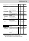
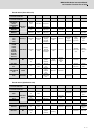
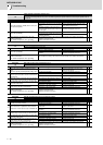
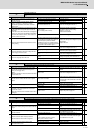
6E
Power supply: H/W error An error was detected in the internal memory.
ARA/D error An error was detected in the A/D converter.
Unit ID error An error was detected in the unit identification.
6F Power supply error
No power supply is connected to the drive unit, or a communication error was
detected.
AR
(Note 4)
70 Power supply: External emergency stop error
A mismatch of the external emergency stop input and NC emergency stop
input continued for 30 seconds.
PR
71 Power supply: Instantaneous power interruption The power was momentarily interrupted. NR
72 Power supply: Fan stop
A cooling fan built in the power supply unit stopped, and overheat occurred in
the power module.
PR
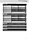
73 Power supply: Over regeneration
Over-regeneration detection level became over 100%. The regenerative
resistor is overloaded. This alarm cannot be reset for 15 min from the
occurrence to protect the regeneration resistor. Leave the drive system
energized for more than 15 min, then turn the power ON to reset the alarm.
NR
74 Power supply: Option unit error An alarm was detected in the power backup unit (power supply option unit).
NR
(Note 3)
75 Power supply: Overvoltage
L+ and L- bus voltage in main circuit exceeded the allowable value. As the
voltage between L+ and L- is high immediately after this alarm, another alarm
may occur if this alarm is reset in a short time. Wait more than 5 min before
resetting so that the voltage drops.
NR
76
Power supply: Function setting error
The rotary switch setting of external emergency stop is not correct, or a wrong
external emergency stop signal is input.
AR
Power supply: Function selection error Undefined area for the rotary switch is selected
77 Power supply: Power module overheat Thermal protection function in the power module has started its operation. PR