


6 - 27
MDS-D2/DH2 Series Instruction Manual
6.1 Adjustment Procedures for Each Control
6.1.8 Spindle Synchronization Adjustment (For Lathe System)
(1) Setting the gain, changeover rotation speed and time constant
[1] For speed loop gain during spindle synchronization, SP005 (speed loop gain 1), SP006 (speed loop lead
compensation 1), and SP007 (speed loop delay compensation 2) are used. For position loop gain, set
standard 15 to SP003 (position loop gain spindle synchronization).
(Note1) To change the setting value of SP003, set the synchronous and basic spindles to the same value.
(Note2) For the adjustment of SP005, SP006 and SP007, conduct "Adjusting the speed loop parameter" as
a single unit beforehand.
[2] Set rotation speed and time constant during acceleration/deceleration figured by theoretical calculations.
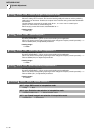
[3] Set "Time-series data measurement" with NC Analyzer as follows and output speed feedback and current
command.
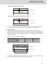
< NC Analyzer setting (Time-series data measurement) >
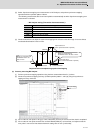
(2) Confirming the current margin
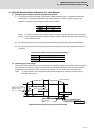
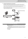
Perform acceleration/deceleration up to the maximum current speed in spindle synchronization mode. At this time,
confirm that the current value for both acceleration side and deceleration side secure 30% or more of margin in
respect to the current limit value. Also, confirm that no oscillation, etc. are found in the current waveforms.
(Note) If a margin is 30% or less, extend the acceleration/deceleration time constant so that the margin is
adjusted to 30% or more.
output waveform example in spindle synchronous mode
Parameter Setting value
SP003 15
SP036 0000
Get Waveform type
CH1 Speed feedback (r/min)
CH2 Current command
0
0
Current margin has to
be 30% or more.
Current margin has to be
30% or more.
SP152 or SP186
Speed feedback
Current command
SP153 or SP185
Current limit at accelaration
Current limit at regeneration