


7 - 22
7 Troubleshooting
MITSUBISHI CNC
Alarm No.
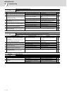
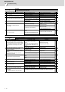
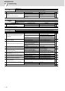
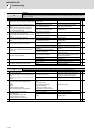
41
Feedback error 3
Either a missed feedback pulse in the main side incremental encoder or an error in the Z-phase was detected in the full closed
loop system. In the servo, Z-phase was not detected by a rotary encoder within 2 rotations.
Investigation details Investigation results Remedies SV SP
1
Check the connection condition of the cable and
encoder.
- Check if the cable is disconnected.
The cable is disconnected. Replace the cable.
◯◯
The cable is normal.
Check for dirt on the connector terminal and
reconnect it.
The alarm occurs even after it is
reconnected.
Replace the encoder.
Alarm No.
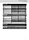
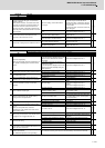
42
Feedback error 1
An error was detected in the sub side encoder (feedback signals of the position encoder in a servo system, or PLG's feedback
signals in a spindle system).
Investigation details Investigation results Remedies SV SP
1 Check SP019 and SP020.
Parameter is set incorrectly. Correctly set.
◯
Parameter is set correctly. Check the investigation item No. 2.
2 Check the alarm No. "2C" items.
◯
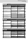
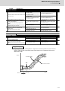
Alarm No.
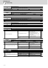
43
Feedback error 2
Excessive difference was detected in position data between the motor side encoder and the machine side encoder.
Investigation details Investigation results Remedies SV SP
1
Check if the connecting pulley ratio of the spindle
end to ABZ pulse encoder meets the machine
specifications.
The pulley ratio of the spindle end to encoder
is 1:1.
Check the parameter setting.
◯
The spindle end and encoder are not equal in
the pulley ratio.
Check the parameter setting.
When the encoder is smaller than the spindle
end in the pulley ratio, replace the pulley.
No problem. Check the investigation item No. 2.
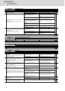
2
Check the setting value of the spindle parameter
from SP057 to SP064.
The correct values are not set. Correctly set.
◯
The correct values are set. Check the investigation item No. 3.
3 Check the spindle parameter SP054 setting value.
V-belt is used for the spindle end driving. Set "-1" to the spindle parameter "SP054".
◯
Other than V-belt (gears or timing belt) is
used for the spindle end driving.
Set "360" to the spindle parameter "SP054".
SP054 is set corresponding to the machine
specifications.
Check the investigation item No. 4.
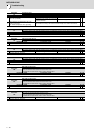
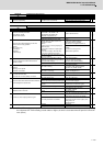
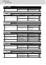
4
Jiggle the encoder connectors (drive unit side and
encoder side) and check if they are disconnected.
The connector is disconnected (or loose). Correctly install.
◯◯
The connector is not disconnected. Check the investigation item No. 5.
5
Is the encoder cable wired in the same conduit as
the motor's power cable, or are the two cables laid
in parallel near each other?
The cables are wired near each other. Noise
is entering from the power cable.
Improve the cable wiring.
Divide it by a FG shield.
◯◯
The wires are sufficiently separated. Check the investigation item No. 6.
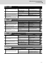
6
Is the motor FG wire connected only to the drive unit
which drives it?
(Is the motor grounded to one point?)
The motor FG wire is grounded on the motor
side.
Ground the motor to one point, connecting
the wires together on the drive unit side.
◯◯
The motor is grounded to one point. Check the investigation item No. 7.
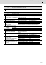
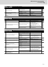
7
Turn the power OFF, and check the encoder cable
connection with a tester. (Is the cable shielded?)
The connection is faulty. Replace the encoder cable.
◯◯
The connection is normal. Check the investigation item No. 8.
8
Replace with another unit, and check whether the
fault is on the unit side or encoder side.
The alarm is on the drive unit side. Replace the drive unit.
◯◯
The alarm is on the encoder side. Check the investigation item No. 9.
9
Check if there is any abnormality in the encoder's
ambient environment.
(Ex. Ambient temperature, noise, grounding)
Take remedies according to the causes of the abnormality in the ambient environment.
◯◯
10 Check SP019, SP020, SV019, and SV020.
Parameter is set incorrectly. Correctly set.
◯◯
Parameter is set correctly. Check the investigation item No. 11.
11 Check the alarm No. "1B" items.
◯